7
Unit Description
The Thermo King V250 is a truck refrigeration system that
is designed for low and medium temperature applications
on medium-sized trucks. There are two basic models:
• Model 10: Cool and defrost on engine-driven compres-
sor operation.
• Model 20: Cool and defrost on both truck engine-
driven and electric standby compressor operation.
The system consist of three separate assemblies: the con-
denser, the evaporator, and the compressor.
The condenser has a unique design that allows it to be
mounted horizontally or vertically, on the roof or on the
front of the truck box.
The evaporator is mounted inside the truck box. Funnel and
thin-line evaporators are available. The funnel evaporator
mounts on the ceiling or the front wall. The thin-line evapo-
rator mounts on the front wall.
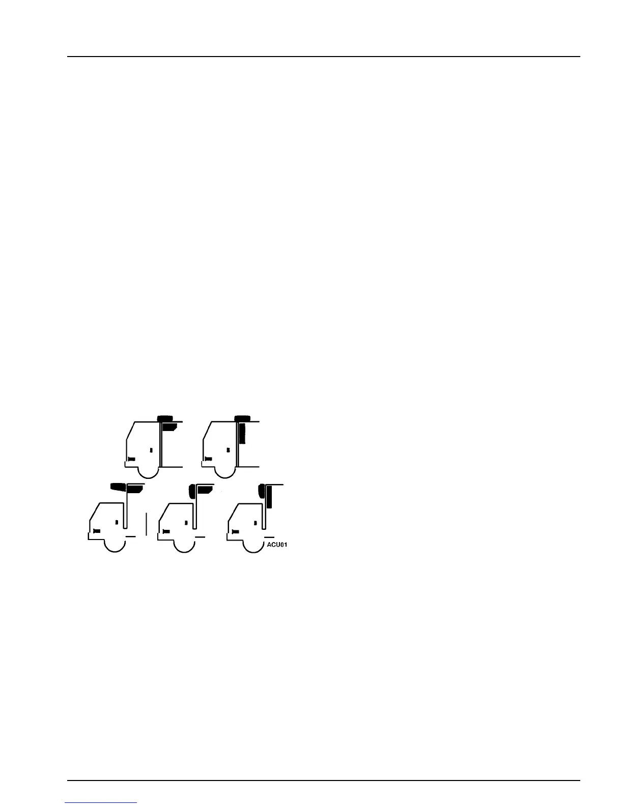
Condenser and Evaporator Configurations
The compressor is mounted on and driven by the truck
engine. Refrigeration hoses or lines are used to connect the
condenser, the evaporator and the compressor. Model 20
units have another compressor and an electric motor
mounted in the condenser section for electric standby
operation.
The electric standby compressor is connected in parallel
with the engine-driven compressor. The engine compressor
is driven by a belt from the engine. The standby compressor
is driven by a belt from the electric motor. Both compres-
sors use the same refrigeration system circuit. Check valves
isolate one compressor from the other during operation.
Compressor operation is controlled by the thermostat,
which energizes the compressor clutch during engine opera-
tion or starts the electric motor and energizes the compres-
sor clutch on electric standby operation. The refrigeration
system is protected by a high pressure cutout switch and a
low pressure cutout switch.
The control circuits operate on 12 volts dc supplied by the
truck battery for over-the-road operation. On standby oper-
ation, the power is rectified from an ac transformer.
The cab control box is mounted in the truck cab. It contains
the On-Off key, Manual Defrost key, thermometer, thermo-
stat, and indicator lights.
Liquid Injection System
If the discharge gas leaving the engine driven compressor
reaches a temperature of 230 ± 5 F (110 ± 3 C), the liquid
injection switch closes, providing voltage to the liquid injec-
tion solenoid. The solenoid opens a valve, allowing liquid
refrigerant to flow from the liquid line near the receiver out-
let valve to the metering orifice attached to the suction fit-
ting at the compressor. As the refrigerant passes through the
metering orifice it expands and evaporates, cooling the suc-
tion gas entering the compressor. This cooling effect is
transferred to the discharge gas leaving the compressor from
the adjacent cavity in the compressor head. When the dis-
charge gas is cooled to 200 ± 5 F (93 ± 3 C), the liquid injec-
tion switch opens, the liquid injection solenoid valve closes
and refrigerant no longer flows through the liquid injection
system.

 Loading...