23
Operating Instructions
UNIT CONTROLS
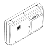
Cab Control Box
1. ON-OFF KEY. Press this key to turn the unit ON and
OFF.
2. ON INDICATOR. When this light is on, it indicates
that the unit is turned ON. When this light is off, it
indicates that the unit is turned OFF.
3. POWER CORD INDICATOR. When this light is on, it
indicates that the unit is connected to an electric
standby power source.
4. RUNNING INDICATOR. When this light is on, it
indicates that the unit is running.
5. MANUAL DEFROST KEY. Press this key to start a
defrost cycle. The unit will not defrost unless the
defrost termination switch is closed (evaporator coil
temperature below 42 F [5.6 C]).
6. DEFROST INDICATOR. When this light is on, it indi-
cates that the unit is in defrost.
7. DIGITAL DISPLAY. This display is active only when
the unit is turned on. The thermometer reading (return
air sensor temperature) normally appears on the dis-
play. Pressing the setpoint key causes the thermostat
setpoint to appear on the display for 10 to 15 seconds.
8. HEAT INDICATOR. When this light is on, it indicates
that the unit is running in heat.
9. COOL INDICATOR. When this light is on, it indicates
that the unit is running in cool.
10. CELSIUS INDICATOR. When this light is on, it indi-
cates that the temperature is being displayed in degrees
Celsius.
11. FAHRENHEIT INDICATOR. When this light is on, it
indicates that the temperature is being displayed in
degrees Fahrenheit.
12. AC OVERLOAD INDICATOR. When this light is on,
it indicates that the overload relay has opened. This
indicator must be reset by pressing the On-Off Key
after allowing time for the overload relay to cool.
13. SETPOINT KEY. Press this key to make the thermo-
stat setpoint appear on the digital display. The thermo-
stat setpoint will remain on the display for 10 to 15
seconds after the key is released. This gives the opera-
tor time to adjust the thermostat setpoint.
14. THERMOSTAT DIAL. Turn this dial to adjust the
thermostat setpoint.
NOTE: The Thermostat Dial will change the thermo-
stat setpoint without pressing the Setpoint Key.
Low Voltage Box
1. DEFROST TIMER. The defrost timer is built-in to the
PC board. It can automatically initiate or terminate a
defrost cycle if necessary. The initiation interval is
adjustable from 1 hour to 10 hours. The termination
interval is set at 45 minutes. Refer to the Electrical
Maintenance section for more information about the
defrost timer.
2. CONTROL RELAYS. Six control relays are located
on the PC board. These relays are used to control the
operation of the unit.
3. ENGINE HOURMETER (Optional). This hourmeter
records the amount of time the unit runs on engine
operation.
4. ELECTRIC HOURMETER (Model 20) (Optional).
This hourmeter records the amount of time the unit runs
on electric standby operation.
High Voltage Box (Model 20)
1. MOTOR CONTACTOR. The motor contactor is used
to control the operation of the electric motor that drives
the electric standby compressor.

 Loading...


