Electrical Maintenance (Rev 1/99)
31
Testing the Cab Control Box
The cab control box contains the thermometer and the ther-
mostat. The thermometer and the thermostat share the same
digital display and use the same sensor. The thermometer
displays the sensor temperature. The thermostat compares
the sensor temperature with the setpoint to determine the
unit’s operating mode. The sensor is normally located in the
evaporator return airflow.
Thermometer
The range for the thermometer is -40 to 99 F (-40 to 38 C).
Normally the thermometer reading appears on the digital
display. Pressing the Setpoint key causes the thermostat
setpoint to appear on the digital display for 10 to 15
seconds.
Thermostat
The setpoint range for the thermostat is -26 to 86 F (-32 to
30 C) or -8 to 86 F (-22 to 30 C). The thermostat setpoint
appears on the digital display when the Setpoint key is
pressed. Turning the thermostat dial changes the setpoint.
The thermostat controls the operation of the unit by control-
ling the power relay, the heat relay, and the electric relays.
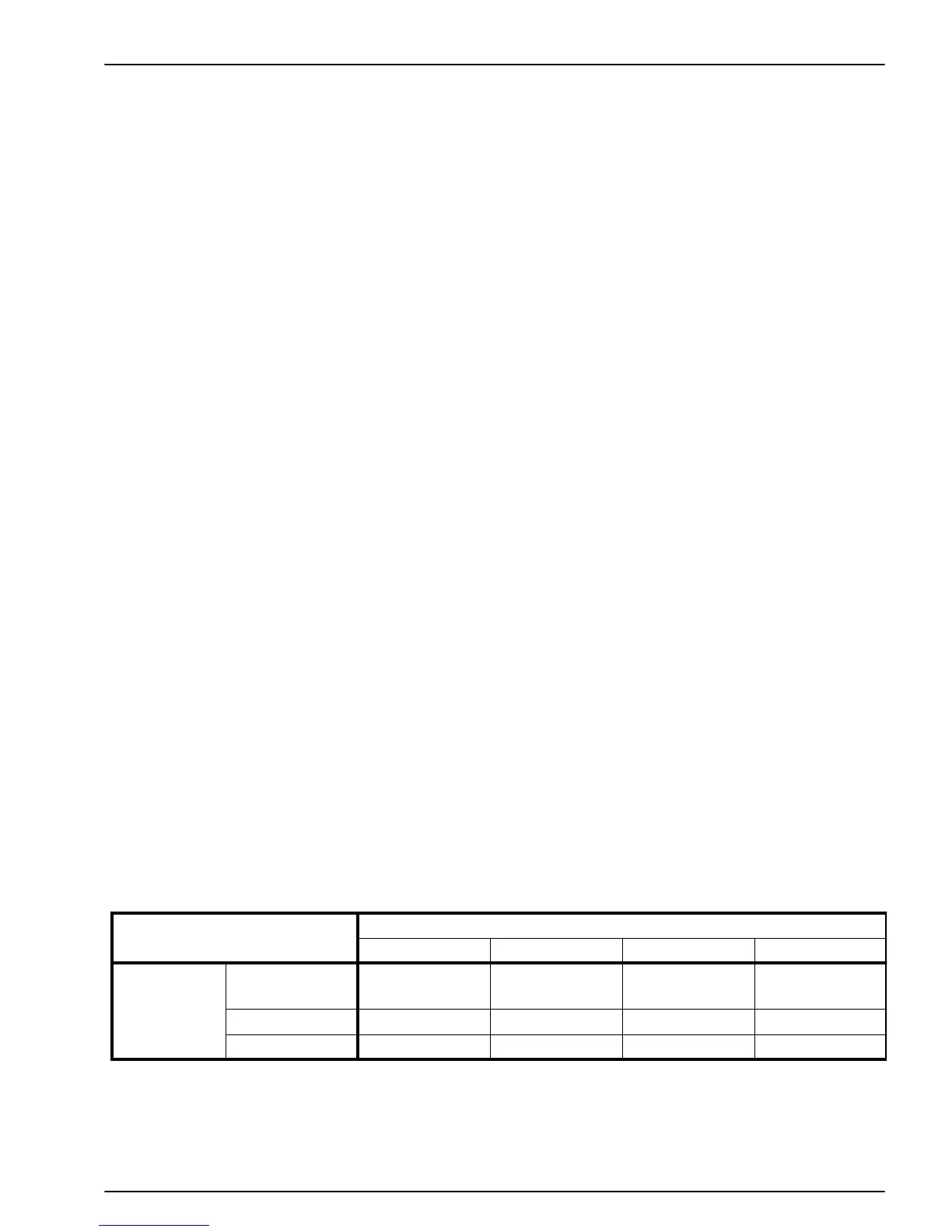
Display Diagnosis Chart
Setpoint Display
Normal Display Blank Display Erratic Display No Change
Temperature
Display
Normal Display
No Problem Faulty Cab
Control Box
Faulty Cab
Control Box
Faulty Cab
Control Box
Blank Display Check Sensor Check Power Check Power Check Power
Erratic Display Check Sensor Check Power Check Power Check Power
Initial Digital Display Test
1. Turn the unit ON. Note what appears on the digital dis-
play. This is the temperature display.
a. Normal Display (-40 to 199 F [-40 to 38 C])
b. Blank Display
c. Erratic Display
2. Press the Setpoint key and note what appears on the
digital display. This is the setpoint display.
a. Normal Display (-26 to 86 F [-32 to 30 C])
b. Blank Display
c. Erratic Display
d. No Change
3. Refer to the Display Diagnosis Chart to see what to
check next.
Check Power—Engine Operation
1. Make sure that the condenser cover is on the unit.
2. Remove the cover from the back of the cab control box.
3. Start the truck engine and turn the unit ON.
 Loading...