Refrigeration Service Operations (Rev 1/99)
64
4. Install the coil on the solenoid valve and connect the
wires.
5. Open the refrigeration valves.
OIL SEPARATOR
Removal
1. Remove the refrigerant charge.
2. Disconnect the ORS nuts at the end of the oil separator.
3. Loosen the mounting hardware and remove the oil sep-
arator.
Installation
1. Soak new o-rings in refrigerant oil (same type that is
used in the system) and place the new rings in the ORS
fittings on the ends of the oil separator.
2. Install and tighten the inlet and outlet ORS nut.
3. Hold the oil separator with a backup wrench on the hex
behind the ORS fitting.
4. Pressurize the refrigerant system and check for leaks.
5. If no leaks are found, evacuate the system.
6. Recharge the unit.
NOTE: Used when oil separator is routed to evapora-
tor section for testing. Use as a tool only. do not leave
in unit.
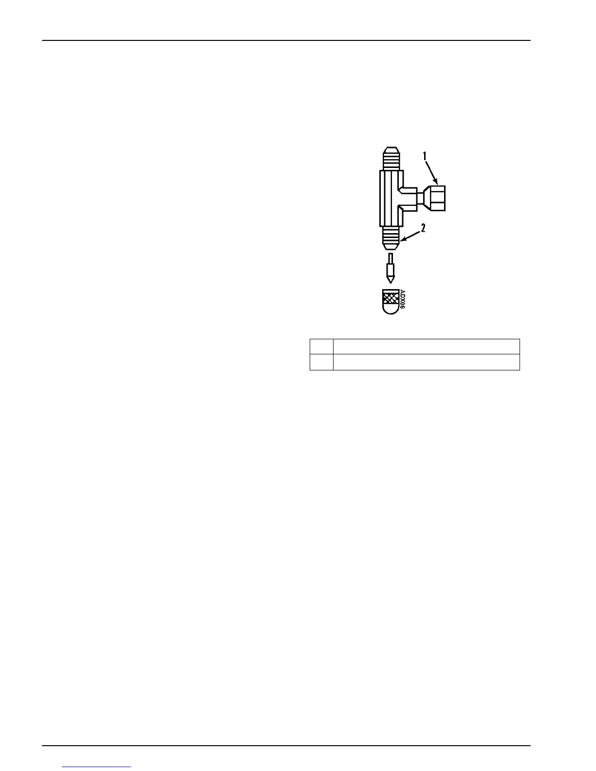
Tee-Fitting for V250 Suction Line Access
LIQUID INJECTION METERING ORIFICE
Removal
1. Pump down the low side and equalize the pressure to
slightly positive.
2. Disconnect the refrigeration hose from the metering
orifice and remove the metering orifice from the suc-
tion hose fitting.
NOTE: Take caution to avoid the danger of liquid
refrigerant escaping when the line is disconnected.
1. 1/4 Flare (w/Permanent Depressor)
2. 1/4 Flare SAE 45° Flare (TYP)

 Loading...