Refrigeration Maintenance (Rev 1/99)
58
CLEANUP PROCEDURE FOR SMALL
TRUCK UNITS
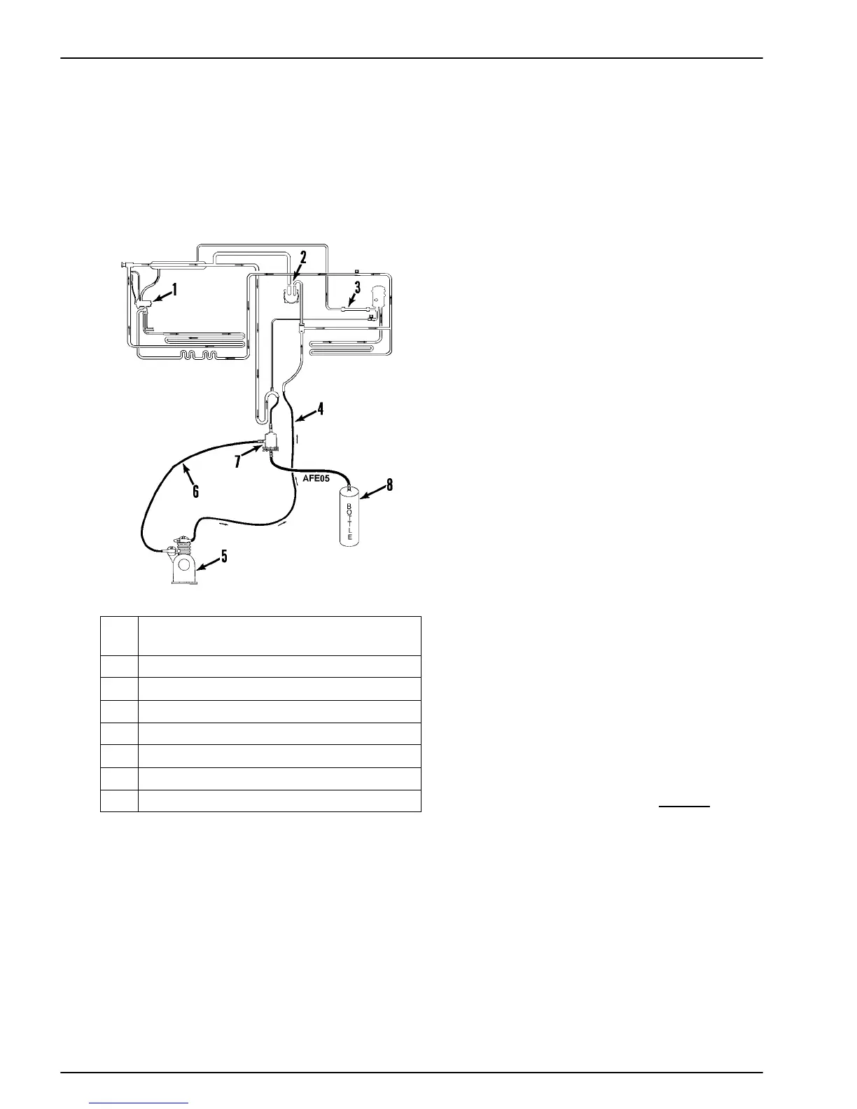
Connecting Flushing Compressor to Unit
NOTE: If a Van Steenburgh reclaimer is available, do not
use this procedure. Follow procedure described in Service
Bulletin T&T 134.
1. Remove Internal Parts From Expansion
Valve
2. Disconnect and Cap (If So Equipped)
3. Replace Drier With Tube
4. Discharge Line
5. Flushing Compressor
6. Suction Line
7. Suction Oil
8. Recovered Oil
Tools Required:
• Motor-driven TK 214 “Flushing Compressor”
• Suction Line Filter (P/N 204-498 with Filter P/N 66-
2988)
• Pipes (In Place of Oil Separator, Check Valve, Oil Sep-
arator and Standby Compressor)
Clean-up Procedure
1. Make sure all hose routing is correct.
2. Make sure that the oil trap is correctly installed.
3. Recover contaminated refrigerant from system.
4. Remove lines from compressors roadside and standby).
5. Flush each compressor using the flushing compressor
and an HFC refrigerant. (Always recover the refrigerant
before disconnecting flushing compressor.)
6. Remove check valve (or check valve seats) from sys-
tem to ensure flow in all directions.
7. Remove oil separator and install a connecting pipe.
8. Remove internals from expansion valve.
9. Open suction pressure regulator (CPR) valve to highest
setting.
10. Install temporary suction line filter (P/N 204-498 and
P/N 66-2988) in suction line.
11. Install connecting pipe in place of standby compressor.
12. Connect flushing system to roadside
discharge and
suction line (see illustration).
13. Evacuate the system and check for leaks. Continue to
evacuate to remove moisture and air.
14. Install HFC refrigerant and flush the system. (Energize
defrost solenoid during 30% to 40% of the clean-up.
Solid contaminants will collect in the suction line filter.
Oil from the system and from the flushing compressor

 Loading...