Electrical Maintenance (Rev 1/99)
49
24. With cab box display showing “05” degrees LEDs P11,
2, 3, 5, 6, 8, and 10 should light as well as the power
cord indicator on the cab box.
25. When circuit goes into the defrost mode LEDs PL3, 6,
7, 8, and 10 should light.
26. Turn variable resistance until the cab box shows “00”
degrees.
27. LEDs PL3 and 6 should light.
28. Turn the variable resistance until the cab box shows “-
05” degrees.
29. LEDs PL3, 4, and 6 should light as well as the top left
LED in the cab box display.
30. Turn off the cab box and power supply. Move jumpers
from W1 and W2 to W3 and W4. Turn R17 to position
#3.
This test will checkout most circuits on the board. It will not
test a circuit that may be broken or burned out between the
relays and all the connector pins that were not connected to
in this test. To test these, a volt meter or external lights
would have to be connected to each pin and observed for the
proper results.
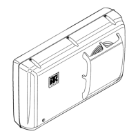
M10 (V250/V-090) Cab Control Box Test
Procedure
1. Connect +12 Vdc Power to pin 3 and negative ground
to pin 9.
2. Connect light bulbs or LEDs between ground and pins
1, 6, and 8.
3. Connect a light bulb or LED between +12 Vdc and pin
10.
4. Connect switches between +12 Vdc and pins 2, 4, 5,
and 7.
5. Connect a variable resistance (620 to 1120 ohms) to the
2 pin sensor connector.
6. With all switches off, apply power to the circuit.
7. With the cab box On/Off switch off, no lights should
come on.
8. Turn on the cab box On/Off switch. The temperature
display should come on.
9. Press the setpoint key once and adjust the setpoint to
“00” degrees.
10. Turn the variable resistance so that temperature read
out is “00” degrees.
11. Only the display, the C or F LED, and the LED in the
ON/OFF switch should be on at this time.
12. Close switch S1 to pin 2. The power cord LED should
come on and PL1 connected to pin 1.
13. Turn variable resistance to indicate 5 degrees on dis-
play.
14. PL2 connected to pin 6 and the LED at the top of the
display between the digits on the cab box should come
on.
15. Close switch S4 to pin 7. The snowflake LED on the
cab box should come on.
16. Close switch S2 to pin 4 and switch S4 to pin 7.
17. Press the defrost key on the cab box. PL3 connected to
pin 8 and the defrost LED on the cab box should come
on but only while this key is being held.
18. Turn the variable resistance to indicate -5 degrees on
the display and open switch S4 to pin 7.
19. PL2 should go off and PL4 connected to pin 10 should
come on. The snowflake LED and the LED at the top of
display between the digits should go off, and the LED
at the top of the display to the left of the digits should
come on.
20. Close switch S3 to pin 5. This should cause the cab box
to shut off and the alarm symbol LED to come on.

 Loading...


