Compressor and Clutch Maintenance (Rev 1/99)
81
After tightening the bolt, ensure that the pulley rotates
smoothly.
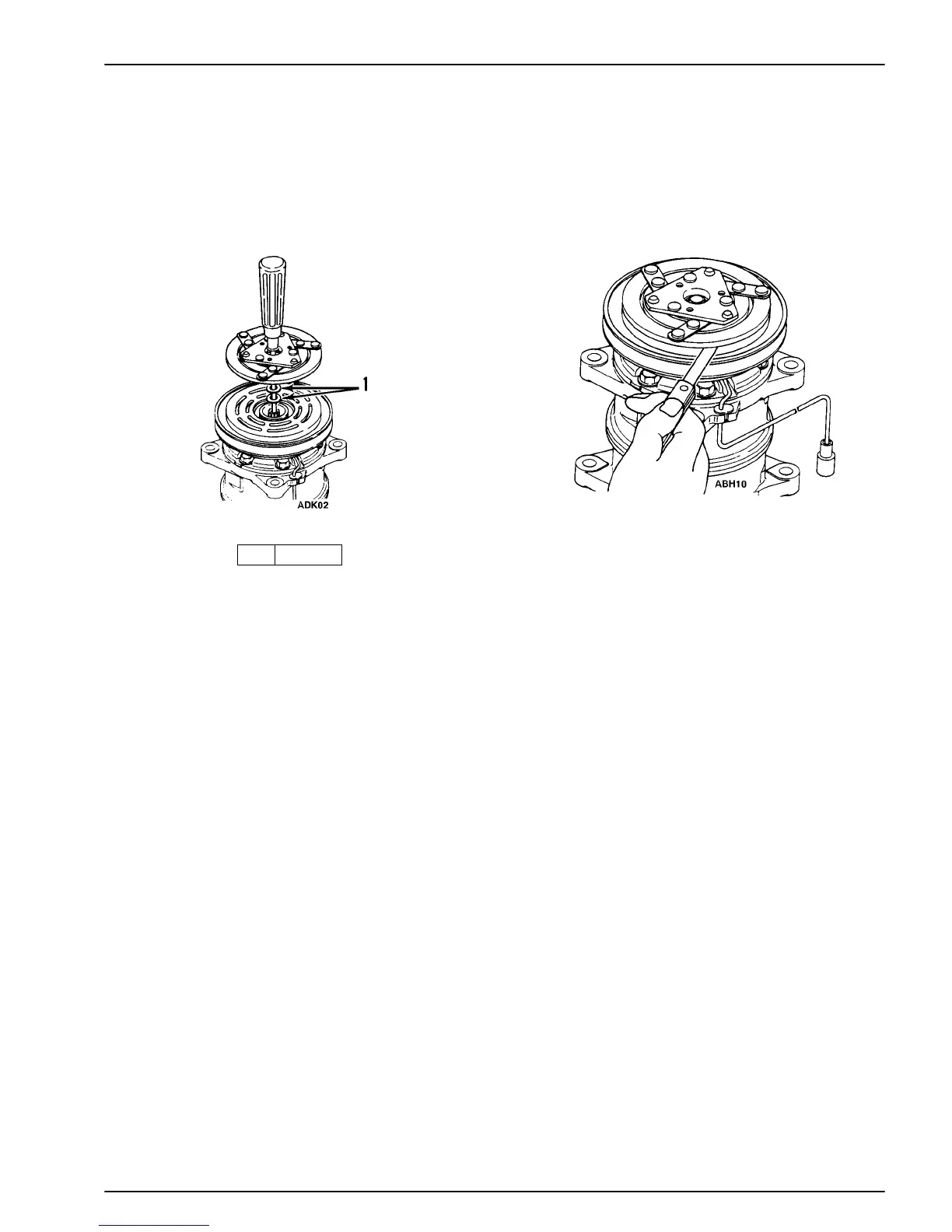
Install Shims and Drive Plate
8. Ensure that the clutch clearance is as specified. If nec-
essary, adjust the clearance using shims.
Adjusting shims are available in the following thick-
nesses:
Shim TK P/N Thickness in. (mm)
TK 11-8031 0.0039 in. (0.1 mm)
TK 11-8032 0.0118 in. (0.3 mm)
TK 11-8033 0.0197 in. (0.5 mm)
1. Shims
NOTE: Specified clearance: 0.01 to 0.02 in. (0.3 to
0.6 mm).
Check Clearance
Electrical Connection
1. Connect the lead wire to the electrical circuit.
NOTE: The stationary field is grounded at the fac-
tory; therefore, it is necessary only to connect the hot
(lead) wire.
2. Engage and disengage the clutch several times to check
the clutch engagement. The disc should snap firmly
against the pulley.
SHAFT SEAL COVER AND SHAFT SEAL:
REMOVAL AND INSTALLATION
Removal
1. Remove the magnetic clutch assembly, as outlined in
“Magnetic Clutch Removal” section of this manual.
2. Remove the felt pad.
3. Use the seal remover (from the shaft seal kit P/N 204-
805) to remove the shaft seal cover. Turn the seal
remover to engage the hook on the seal remover with

 Loading...