5
MountingtheFrontCarrier
Frames
Partsneededforthisprocedure:
2
Carrierframe
2
Spacer
2
Bolt(1/2inchx3-1/4inches)
2
Locknut(1/2inch)
Procedure
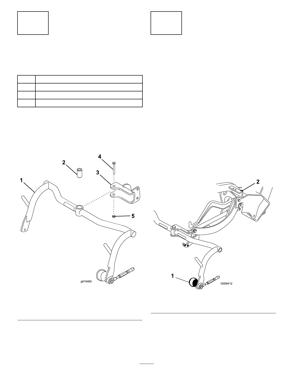
1.Mountacarrierframeassemblytoeachclevis
withaspacer,bolt(1/2x3-1/4inch),andlocknut
(1/2inch);refertoFigure8.Torqueto91to113
N∙m(67to83ft/lb).
g016465
Figure8
1.Carrierframe4.Bolt(1/2x3-1/4inches)
2.Spacer5.Locknut(1/2inch)
3.Clevis
2.Lubricatethebushingsineachcarrierframewith
No.2lithiumgrease.
6
AdjustingtheCarrierFrame
Rollers
NoPartsRequired
Procedure
1.Positionthemachineonalevelsurfaceand
lowerthecuttingunitcarrierframestotheoor.
2.Verifythatthereis13mm(1/2inch)clearance
betweenthecarrierframerollersandtheoor.
3.Ensurethatthecarrierframerollersarelevelto
theground.Iftheyarenotlevel,insertalong
toolintotheendofthecarrierframeandapply
pressureuntiltherollersarelevel.
4.Ifyoumustadjusttheclearance,loosenthe
jamnutonthecarrierframestopscrew(Figure
9)androtatethescrewupordowntoraiseor
lowerthecarrierframe.Tightenthejamnutto
securetheadjustment.
g008412
Figure9
1.Carrierframeroller2.Carrierframestopscrew
13

 Loading...


