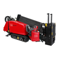
Figure97
2.Stoptheengineandremovetheignitionkey.
3.Removethe4boltsontheguardplateandgearbox
(BoxAofFigure97).
4.Removetheguardplate(BoxAofFigure97).
5.Removethecoveronthegearboxandsyphontheoil
out(BoxBofFigure97).
6.Fillthegearboxwithoiluntiltheoillevelinthesight
glassismorethanhalffull(Figure96).
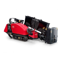
7.Cleanthesealantoffofthegearboxboxandcover
(Figure98).
Figure98
8.Putnewautomotive-gradeRTVsealantaroundthe
edgeofthecover(BoxBofFigure98).
9.Placetheguardbackintoplaceandinstallthe2bolts
(BoxAofFigure97).
10.Installthe2otherboltssecuringthelidontothe
gearbox(BoxAofFigure97).
11.Torquetheboltsto23to29N∙m(17to21ft-lb).
ServicingtheTracks
ServiceInterval:Beforeeachuseordaily—Checkthetrack
tension.
WARNING
Greaseinthehydraulictrackishighlypressurized;
ensurethatthetrack-tensiongreasevalveisnot
loosenedmorethanonerevolutionatatime.
Ifyouremovethetrack-tensiongreasevalvefound
inthehydraulic-tracktensionerorloosenittoo
much,greasecanbereleasedandmaycause
seriousinjuryordeath.
TighteningtheTrackTension
Ifthetrackseemsloose,tightenthetracktensionasfollows:
1.Parkthemachineonalevelsurface,stoptheengine,
andremovetheignitionkey.
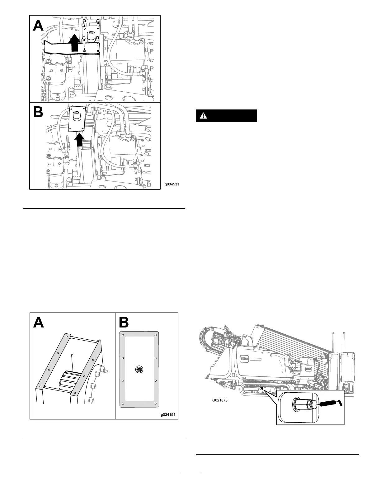
2.Removedirtanddebrisfoundaroundthetrack-tension
greasevalve(Figure99).
Important:Ensurethattheareasurrounding
thetrack-tensiongreasevalveiscleanbefore
beginningtoadjustthetracktension.
3.Removetheretainingboltsandcoverthathousethe
track-tensiongreasevalve.
4.Applygreasetothettinguntilthetensionreaches
22,063kPa(3,200psi)asshowninFigure99.
Figure99
Track-tensiongreasevalveshown
76
 Loading...