260 Series Tractor Service Manual 2 - 7
CHASSIS
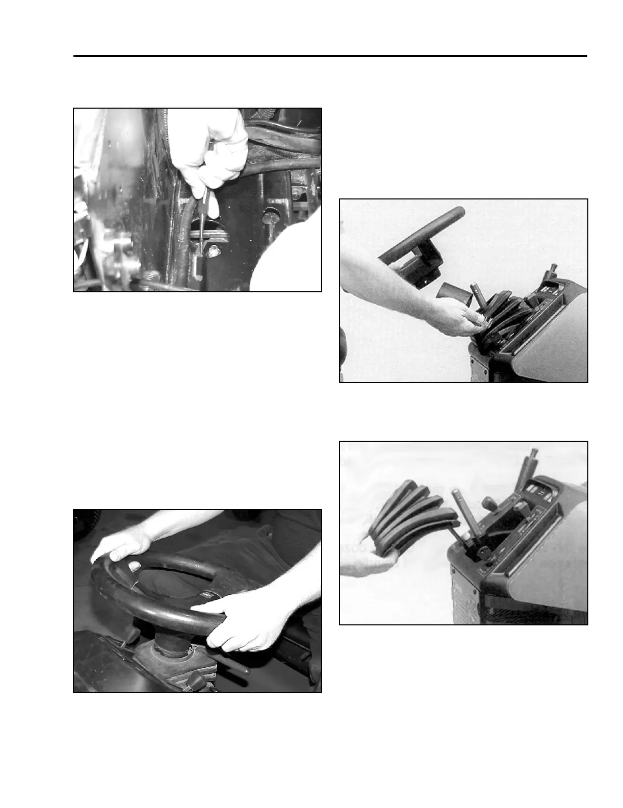
4. Tighten the nut until the eccentric turns with a
small amount of friction (Figure 21).
Figure 24
MVC-113X
5. Using a punch, turn the eccentric clockwise until
zero clearance is obtained between the end of the
steering shaft gear and the steering sector (Figure
24).
6. Tighten the nut to 25 – 35 ft lb (34 – 48 Nm). DO
NOT OVERTIGHTEN.
7. Apply some multipurpose grease to the steering
gear teeth.
8. Connect the tie rod ends to the steering arms.
9. Turn the wheels left and right. Recheck for zero
clearance (Figure 25).
Figure 25
MVC-115X
10. Reinstall the battery tray and battery.
Steering Gear Shaft Disassembly
1. Disconnect the negative battery cable.
2. Remove the roll pin, steering wheel, spacer, and
spring from the top of the steering shaft (Figure
26). (Note: Some units use a retaining nut and
washer located under the center cover of the
steering wheel).
Figure 26
6-9
3. Remove the rubber boot from the steering shaft
and console (Figure 27).
Figure 27
6-10
 Loading...