260 Series Tractor Service Manual 2 - 13
CHASSIS
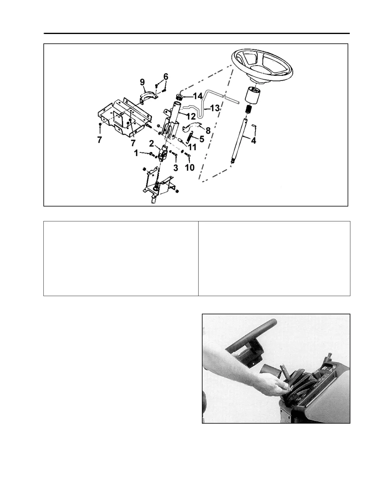
Figure 44 6-35
Tilt Steering Disassembly
1. Remove the roll pin, steering wheel, spacer, and
spring from top of the steering shaft (Figure 45).
(Note: Some units use a retaining nut and washer
located under the center cover of the steering
wheel.)
Figure 45
6-9
(1) Retaining Bolt
(2) Universal Joint
(3) Retaining Bolt
(4) Upper Steering Shaft and Roll Pin
(Note: Some units have retaining nut and washer
located in the center steering wheel cover.)
(5) Spring Extension
(6) Bolts
(7) Nuts
(8) Detent Bracket
(9) Support Bracket
(10) Retaining Bolt
(11) Spacer-Yoke
(12) Column
(13) Tilt Lever
(14) Steering Bushing
 Loading...