CHASSIS
2 - 18 260 Series Tractor Service Manual
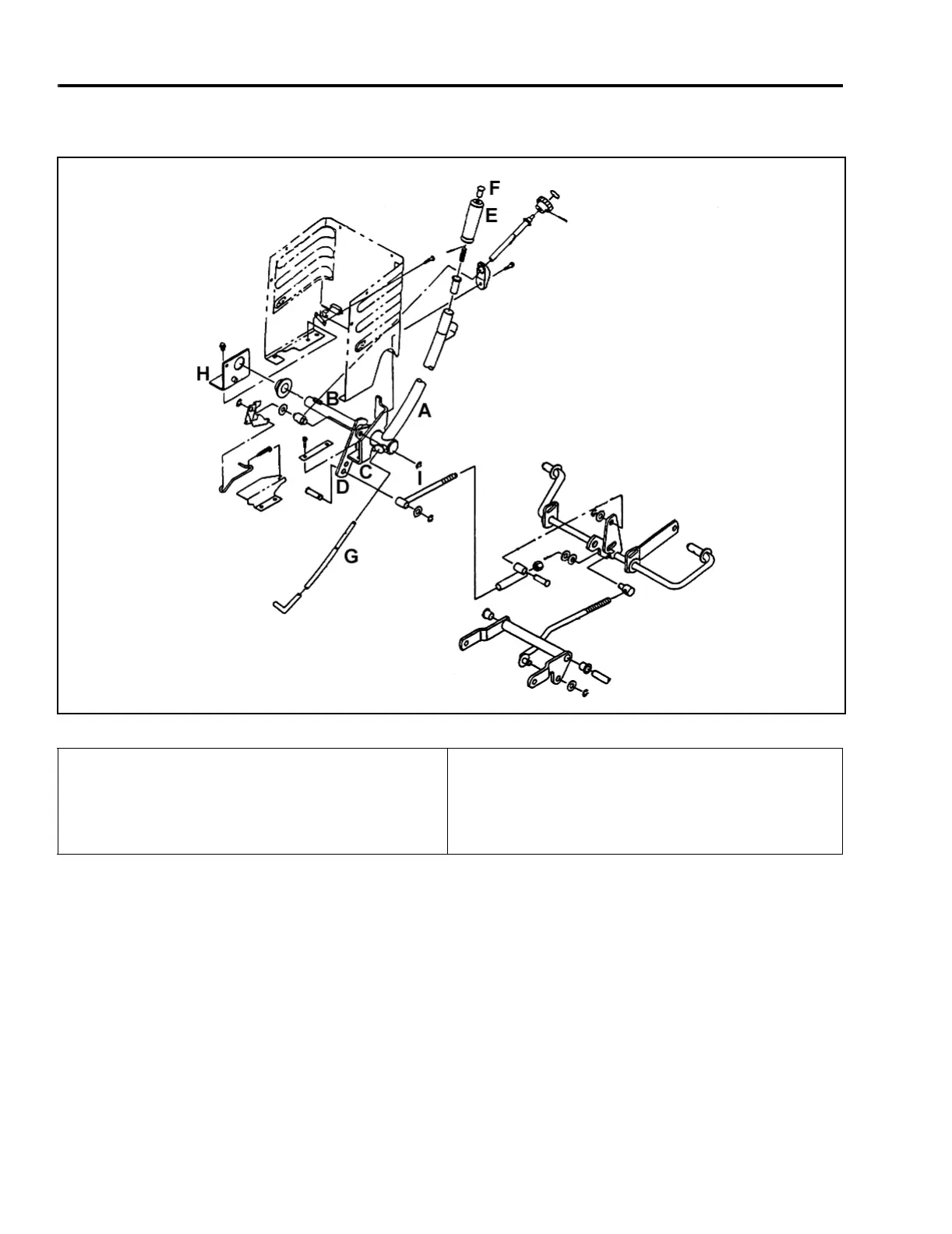
Lift Lever Linkage
Figure 57 7-1
The main components of the lift lever weldment are
the:
•Lift Lever, A
• Lift Arm Cross-Shaft, B
• Mounting Brackets, C and H
• Control Arm, D
The mounting brackets, C and H, secure the lift
weldment to the tractor frame and hold the lift arm
cross shaft, B, in place.
Handle Grip, E; spring-loaded button, F; and rod, G, is
released from its latching socket. This allows the lift
lever to rotate with the lift lever cross-shaft.
When the lift lever is returned to the latched position,
the spring tension pulls rod, G, back into the latching
socket, and the mower deck is secured in the raised
position.
(A) Lift Lever
(B) Lift Arm Cross-Shaft
(C) Mounting Bracket
(D) Control Arm
(E) Handle Grip
(F) Tip Rod Button
(G) Lift Lever Rod
(H) Pivot Linkage Bracket
(I) Lift Rod

 Loading...