6
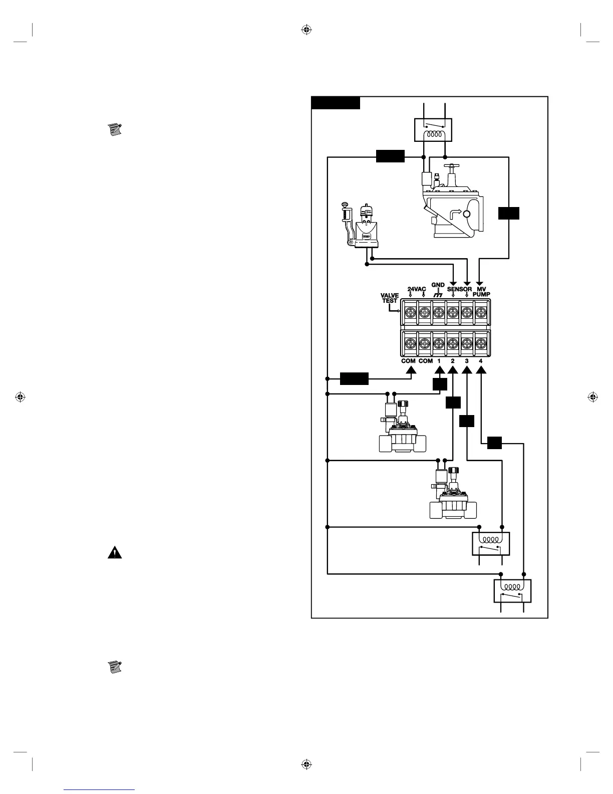
Valve, Pump Relay and Sensor Installation
Figure 13
1
2
3
4
COM
Valve 1
Valve 2
Valve 3 or
Fertilizer Pump 1 Relay
Valve 4 or
Fertilizer Pump 2 Relay
Master Valve
Pump Relay
Rain Sensor
COM
MV
Step 1 – Route valve wires from the valves, master valves, pump
relay and/or sensor into the controller cabinet.
Note: 18 AWG (1.0 mm
2
) multi-wire valve
connection cable can be used. is cable is insulated for
direct burial and is color-coded to simplify installation.
It can be routed directly into the controller through the
access hole provided for valve wire conduit (if conduit is
not used).
Step 2 – Connect valves, master valves and pump start relay
to the valve wires - Connect the white color-coded wire
from the cable to one wire from each valve solenoid and/
or pump relay. (Either of the two wires from the solenoid
or pump relay can be used for this connection.) is
connection will be designated as the valve common wire
(COM).
Connect a separate cable wire to the remaining wire
from each valve solenoid. Note the wire color-code used
for each valve and the valve it controls. You will need
this information when connecting the valve wires to the
controller.
Step 3 – Secure all wire splices using wire nut connectors. To
prevent corrosion and possible short circuits, always use
an insulated wire nut, grease cap or similar waterproong
method.
Step 4 – Connect valve wires to the controller - Secure the valve
common wire (white) to either of the two terminals
labeled COM. Secure the individual valve wires to the
appropriate valves they control, Valve 1 to terminal 1,
Valve 2 to terminal 2, etc.
Step 5 – Connect master valve/pump relay wires to the
controller - Secure the valve common wire (white) to
either of the two terminals labeled COM. Secure the
Master Valve or Pump Relay wire to the terminal labeled
MV/PUMP.
Caution: To prevent controller damage, do not
connect the pump motor starter directly to the controller.
Step 6 – Connect sensor wires to the controller - Remove the
jumper wire from the SENSORS terminals. Secure the
two sensor wires to the sensor terminals. Refer to the
provided sensor instructions for further installation
instructions.
EVOLUTION
®
AG is designed to operate with “normally closed” NC sensors.
Note: For sensors with “normally open” (NO) and “normally closed” (NC) options, select the NC option.
Step 7 – Test for proper operation.
 Loading...