4
Power Supply Installation
WARNING: AC power wiring must be installed and connected by qualied personnel. All electrical components and installation
procedures must comply with all applicable local and national electrical codes. Some codes may require a means of disconnecting from the
AC power source installed in the xed wiring and having a contact separation of at least 0.120" (3mm) in the line and neutral poles. Make
sure the power source is OFF prior to connecting the controller. If the supply cord is damaged, it must be replaced by the manufacturer,
its service agent or a similarly qualied person in order to avoid a hazard.
WARNING: is appliance is not intended for use by persons (including children) with reduced physical sensory, or mental capabilities,
or lack of experience and knowledge, unless they have been given supervision or instruction concerning use of the appliance by a person
responsible for their safety. Children should be supervised to ensure that they do not play with the appliance.
110 VAC Outdoor Models (US and Canada)
Step 1 – Route power and ground wires from a power source through a conduit
Figure 7
Black White Green
110 VAC Outdoor Models
and into the EVOLUTION
®
AG
cabinet.
Step 2 – Open the EVOLUTION
®
AG
controller and access the internal
components.
Step 3 – Remove the power compartment cover to access the transformer wiring.
Remove 1/2" (12.7mm) of insulation from the wire ends.
Step 4 – Using the provided wire nuts, secure the transformer Line (black) wire
to the black power source wire, Neutral (white) to the white power source
wire and Equipment Ground wire (green) to the green power source wire.
Step 5 – Install and secure the power compartment cover.
Step 6 – Apply power to the controller.
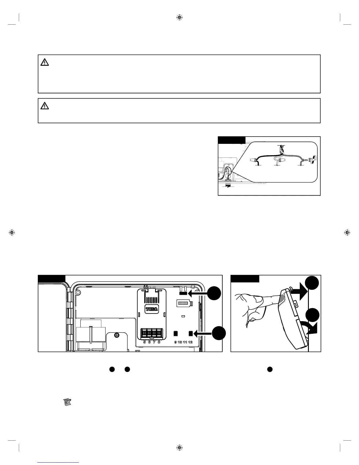
Valve Expansion Module Installation
e EVOLUTION
®
AG controller can be expanded using the optional 4-valve (A-EMOD-4) or 12-valve (A-EMOD-12) modules to add
more valves to the system.
Module Installation
A
A
B
B
Figure 9 Figure 10
Step 1 – Open the EVOLUTION
®
AG
controller door and control panel to access the internal components.
Step 2 – Locate the module slot
A
and
B
. Install the module by placing the bottom hooked standos into slot
A
and push the module
tab towards the cabinet until a positive click is achieved. e click indicates that the module’s retaining tab is fully engaged.
Once installed, the EVOLUTION
®
AG
controller will be able to read the additional valves and will make them available for
scheduling.
Note: If installing only one, four-station module (A-EMOD-4), it must be installed in the valve 5-8 module slot.
 Loading...