Figure 2
1
– Valves and Sensor Terminals
VALVE TEST – Use this terminal to test a valve for proper function.
24VAC – 24 VAC Power Source
GND – Power Source Ground
SENSOR – Sensor Terminals
MV PUMP – Master Valve Terminal
COM – Valves’ and Master Valve Common Terminals
1, 2, 3 and 4 – Valve 1, Valve 2, Valve 3, and Valve 4 Terminals
2
– Valves’ 5, 6, 7 and 8 Expansion Module Socket
3
– Valves’ 9, 10, 11 and 12 Expansion Module Socket
4
– USB Flash Drive Connector
5
– 9 Volt Battery Compartment
6
– Power Supply Terminal Compartment
7
– A-EVO-SC Module (Available Separately)
8
– A-EMOD-4, Four-Valve Expansion Module (Available Separately)
9
– A-EMOD-12, Twelve-Valve Expansion Module (Available Separately)
A
B
C
D
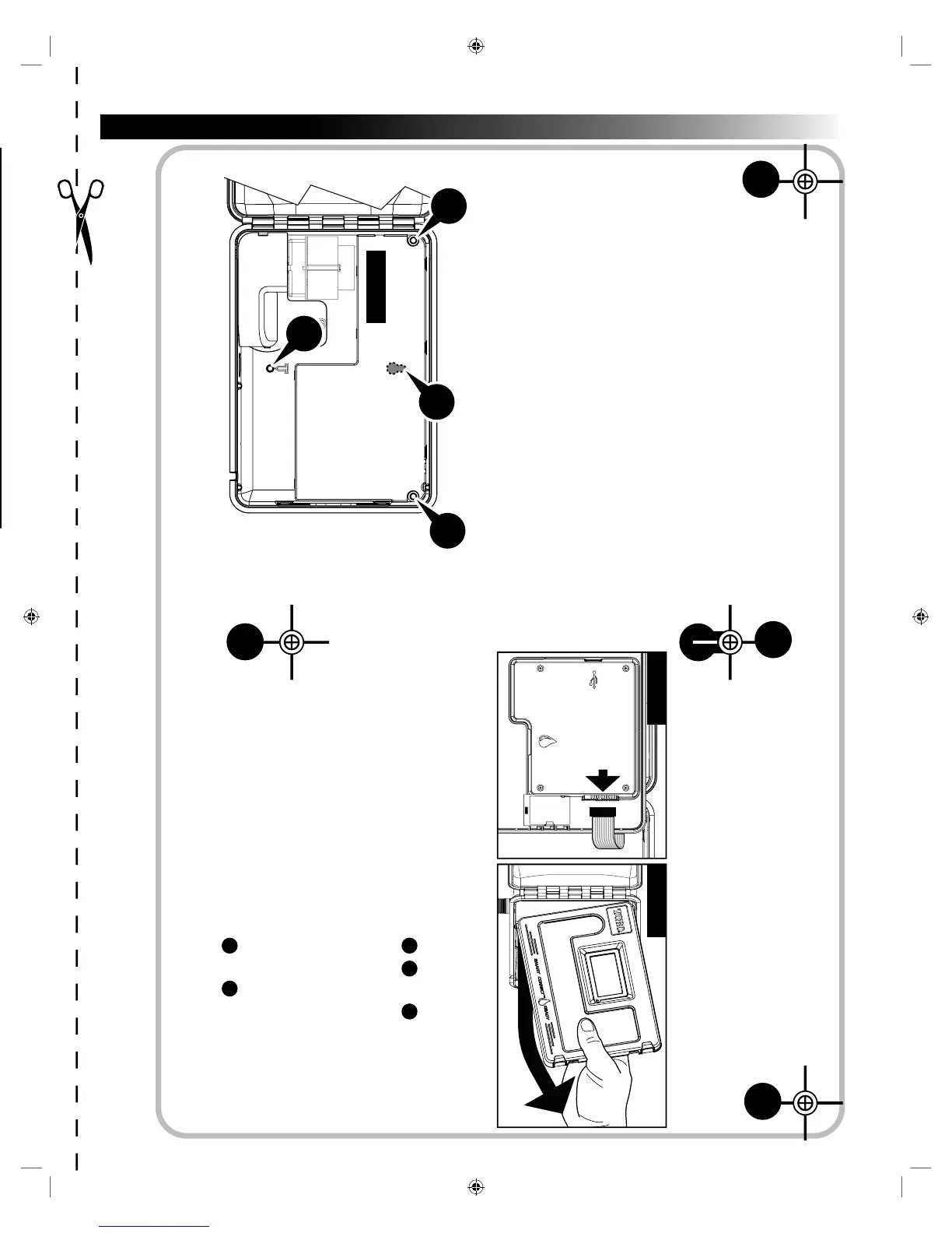
Cabinet Installation
Use this page as a template to mark the screw location of the EVOLUTION
®
AG
cabinet. ere are two mounting options for the EVOLUTION
®
AG. e rst option
allows you to mount the cabinet with three screws and the second option allows you to
mount the cabinet with two screws. For safe and reliable operation, select an installation
site that can provide the following conditions:
• For Outdoor installed controllers - Protection from irrigation spray, wind and snow.
A shaded location is recommended.
• Access to a grounded AC power source that is not controlled by a switch or utilized by
a high current load appliance such as a refrigerator or air conditioner.
• Close proximity to the valve wiring and optional accessory wiring.
A
B
D
C
Option 1
Step 1 – Unplug the controller panel ribbon cable. Open the front panel about
90
º
and detach it from the cabinet by pulling the bottom portion
upwards. Removing it from the cabinet allows you to access the
mounting location.
Step 2 – Mark the mounting screw location
A
,
B
and
D
.
Step 3 – Drill 1/8" (3mm) pilot holes at the marked locations.
Step 4 – Secure the cabinet with screws.
Option 2
Step 1 – Unplug the controller panel ribbon cable. Open the front panel about
90
º
and detach it from the cabinet by pulling the bottom portion
upwards. Removing it from the cabinet allows you to access the
mounting location.
Step 2 – Mark the mounting screw location
C
and
D
.
Step 3 – Drill 1/8" (3mm) pilot holes at the marked locations.
Step 4 – Secure the cabinet with screws.
Figure 3
Figure 4 Figure 5
 Loading...