g299550
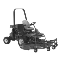
Figure4
1.Wheelhub3.Lugnut
2.Tire
3.Removedthewheelsfromthewheelhubs
(Figure11).
4
InstallingtheLift-Arm
Assembly
ModelNo.31902Only
Partsneededforthisprocedure:
1
Rightliftarm
1
Leftliftarm
2Largepin
2
Bolt(3/8x2-3/4inches)
6
Nut(3/8inch)
2
Smallpin
1
Sensorbracket
2
Carriagebolt
2
Bolt(3/8x1-1/4inches)
2
Greasetting
Procedure
Note:Haveanassistanthelpyoutoinstallthelift
arms,asneeded.
1.Removetheliftarmsfromtheshippingskid.
2.Use2largepinstoinstalltheliftarmstothe
machineframe(Figure5).
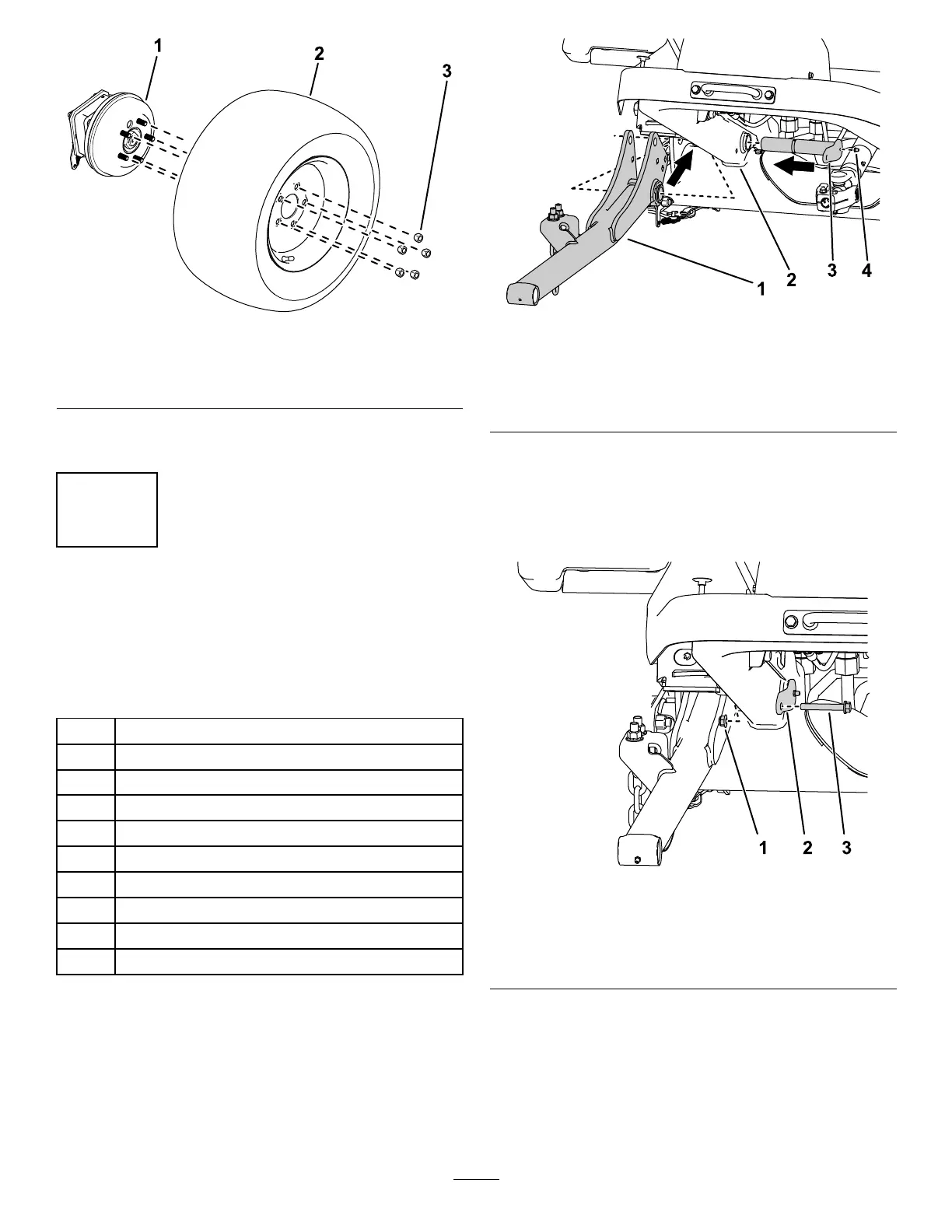
g312023
Figure5
Rightsideshown.
1.Liftarm
3.Largepin
2.Machineframe4.Greasetting
3.Installthegreasettingstothelargepins(Figure
5).
4.Use2nuts(3/8inch)and2bolts(3/8x2-3/4
inches)tosecurethelargepinstotheframe
(Figure6).
g295767
Figure6
Rightsideshown.
1.Nut3.Bolt
2.Largepin
5.Use2carriageboltsand2nuts(3/8inch)to
securethesensorbrackettotherightliftarm
(Figure7).
Note:Ensurethatthesensorbracketdoesnot
interferewiththesensor.
12
 Loading...