15
Adjusting the Height-of-Cut
The height-of-cut is adjustable from 1 to 5 inches (2.5 to
12.7 cm) in 1/2 inch (13 mm) increments. Positioning the
castor wheel axles in the top holes of the castor forks or
pivots (see chart below) allows low range height-of-cut
settings from 1 to 3-1/2 in. (2.5 to 8.9 cm); positioning the
castor wheel axles in the lower holes of the front castor
forks or rear castor pivots (See chart below) allows high
range height-of-cut settings from 2-1/2 to 5 in. (6.4 to
12.7 cm).
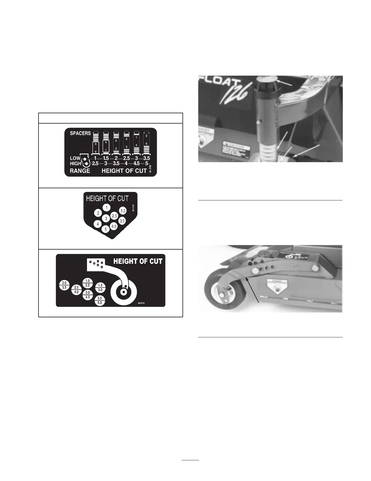
Height-of-Cut Chart
Front Castor Wheels
Rear Deck Straps
Rear Castor Wheels
1. Start the engine and raise the cutting unit so
height-of-cut can be changed. Stop engine after cutting
unit is raised.
2. Position all castor wheel axles in the same holes in the
castor forks or pivots.
Front Castor Wheels
1. Remove HOC cap from spindle shaft and slide spindle
out of front castor arm (Fig. 11). Slide spacers onto
spindle shaft to get desired height-of-cut.
2. Push castor spindle through front castor arm, install
remaining spacers onto spindle, and install HOC cap to
secure assembly (Fig. 11).
Note: On Center deck only, make sure washer remains on
bottom of spindle shaft.
1
2
3
4
Figure 11
1. Front castor wheel
2. HOC cap
3. Spacers
4. Washer (center deck
only)
Rear Castor Wheels
1. Remove hairpin cotter and H.O.C. pin securing rear
castor pivot arm to deck bracket (Fig. 12).
1
Figure 12
1. Rear castor pivot
2. Align the pivot arm holes with selected height-of-cut
bracket holes in the deck frame, install H.O.C. pin and
secure with hairpin cotter.
Rear Deck Straps
1. Lower center and wing cutting units to the ground; then
raise center cutting unit slightly, until rear deck straps
hang freely on wear block of lift arm brackets (Fig. 13).
Stop engine after cutting unit is raised.

 Loading...