45
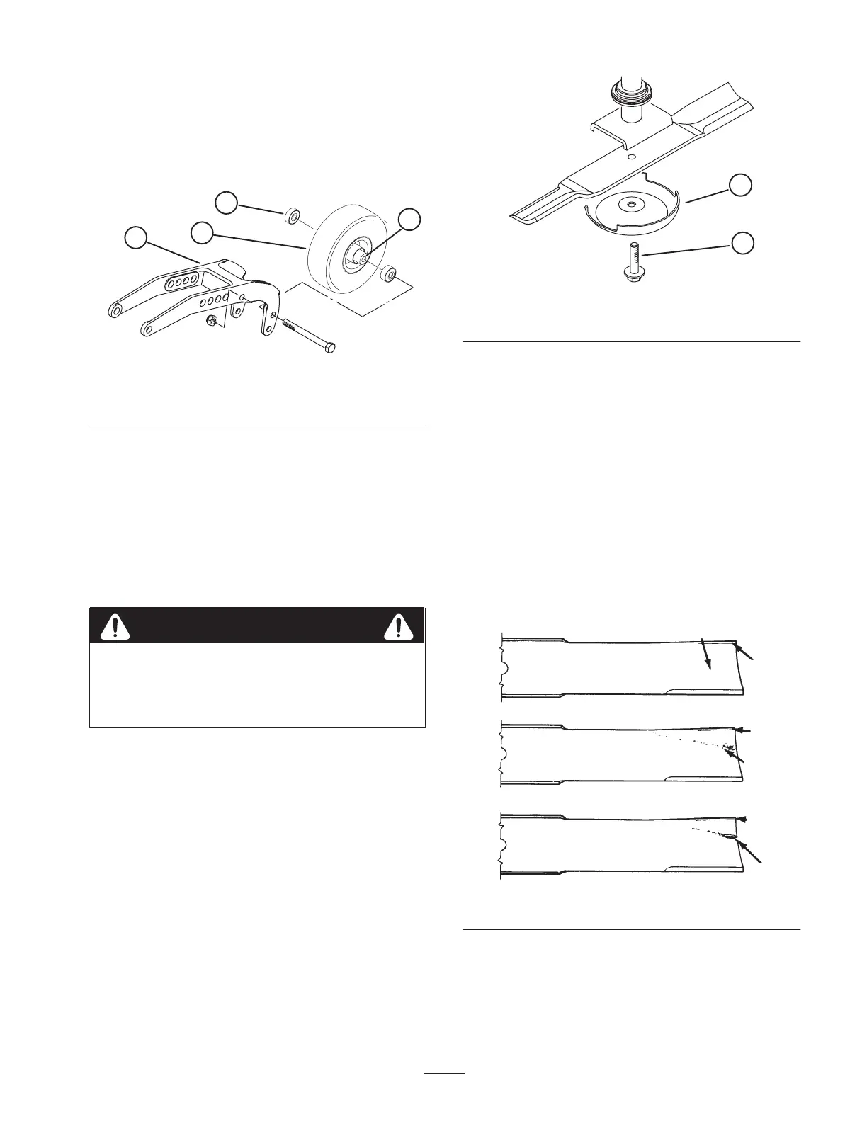
4. To assemble the castor wheel, push bearing into wheel
hub. Slide bearing spacer into wheel hub. Push other
bearing into open end of wheel hub to captivate the
bearing spacer inside the wheel hub.
5. Install castor wheel assembly between castor fork and
secure in place with capscrew and locknut.
1
3
2
4
Figure 79
1. Castor wheel
2. Rear castor pivot arm
3. Bearing (2)
4. Bearing spacer
Removing and Installing the
Blade
The blade must be replaced if a solid object is hit, the blade
is out of balance or if the blade is bent. Always use genuine
Toro replacement blades to be sure of safety and optimum
performance. Never use replacement blades made by other
manufacturers because they could be dangerous.
Do not try to straighten a blade that is bent, and
never weld a broken or cracked blade. Always use
a new blade to assure continued safety certification
of the product.
Warning
1. Raise cutting unit to highest position, shut the engine
off and engage the parking brake. Engage transport
latches to prevent cutting unit from falling accidentally.
2. Grasp end of blade using a rag or thickly padded glove.
Remove blade bolt, anti-scalp cup, and blade from
spindle shaft.
3. Install blade, sail facing toward cutting unit, with
anti-scalp cup and blade bolt. Tighten blade bolt to
85–110 ft.-lb. (116–150 N⋅m).
1
2
Figure 80
1. Blade bolt 2. Anti-scalp cup
Inspecting and Sharpening the
Blade
1. Raise cutting unit to highest position, shut the engine
off and engage the parking brake. Engage transport
latches to prevent cutting unit from falling accidentally.
2. Examine cutting ends of the blade carefully, especially
where the flat and curved parts of the blade meet
(Fig. 81-A). Since sand and abrasive material can wear
away the metal that connects the flat and curved parts of
the blade, check the blade before using the machine. If
wear is noticed (Fig. 81-B), replace the blade; refer to
Removing and Installing the Blade, page 45.
A
B
C
SAIL
SAIL
FLAT PART
OF BLADE
SLOT
FORMED
WEAR
SAIL
Figure 81

 Loading...