19
Parking Brake Latch
A knob on the left side of console (Fig. 18) actuates
parking brake lock. To engage parking brake, connect
pedals with locking pin, push down on both pedals and pull
parking brake latch out. To release parking brake, depress
both pedals until parking brake latch retracts.
Steering Wheel Tilt Lever
Lever on left side of console (Fig. 18) allows steering
wheel to be adjusted for operator comfort.
Transport Latches
Four latches (Fig. 19) secure cutting unit and wings in
upright position for transport operation.
1
Figure 19
1. Transport latch
Hour Meter
The hour meter (under the hood) shows total hours that
machine has been operated.
Horn
The horn is in center of steering wheel. Operates only when
key switch is in ON.
Starting and Stopping
1. Sit on the seat, keep foot off traction pedal. Ensure that
the parking brake is engaged, traction pedal is in
NEUTRAL, and cutting unit engagement switch is in
the DISENGAGED position.
2. Turn ignition switch to ON position. When glow plug
indicator light goes off, engine is ready to START.
3. Turn ignition key to START. Release key when engine
starts.
4. To stop, disengage and move all controls to NEUTRAL
and set parking brake. Turn key to OFF and remove it
from switch. Raise and latch all cutting units in
transport position.
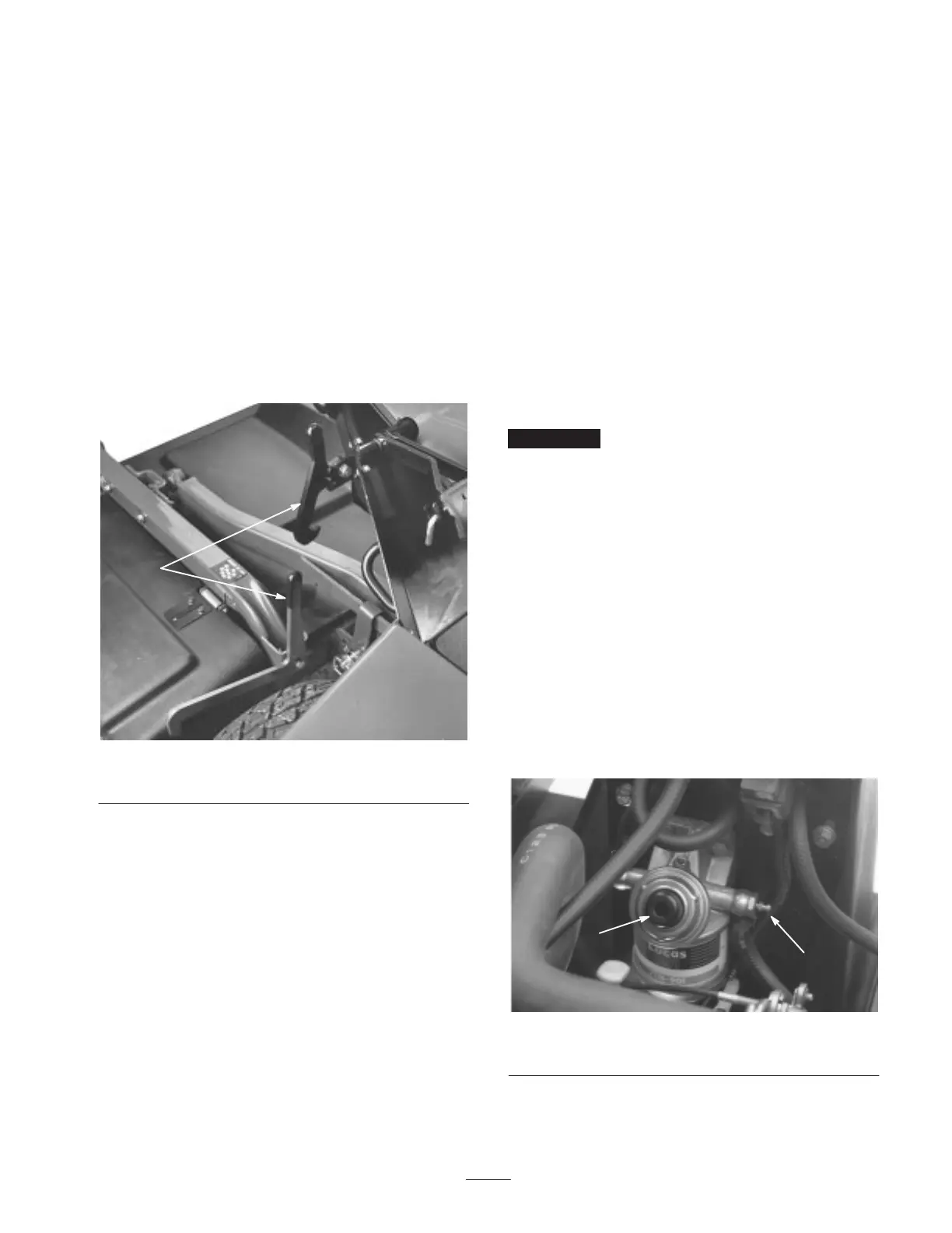
Priming the Fuel System
Important The fuel system may need to be primed
when a new engine is started for the first time, if it runs out
of fuel or if maintenance is performed on the fuel system.
1. Unlatch and raise hood.
2. Insert a 3/16 in. hose over bleed screw and run other
end into a container to catch fuel.
3. Loosen fuel filter/water separator bleed screw (Fig. 20)
a few turns. Pump priming plunger until a steady stream
of fuel comes out of hole in bleed screw. When fuel
stops foaming, tighten the bleed screw during the
downstroke of the priming plunger. Wipe up any spilled
fuel.
Note: Priming fuel filter without opening bleed screw may
damage priming plunger.
4. Pump priming plunger until resistance is felt. Try to
start engine. If engine does not start repeat step 3.
1
2
Figure 20
1. Primer plunger 2. Bleed screw

 Loading...