Cooling System
Maintenance
Cooling System Safety
• Swallowing engine coolant can cause poisoning;
keep out of reach from children and pets.
• Discharge of hot, pressurized coolant or touching
a hot radiator and surrounding parts can cause
severe burns.
– Always allow the engine to cool at least 15
minutes before removing the radiator cap.
– Use a rag when opening the radiator cap, and
open the cap slowly to allow steam to escape.
• Do not operate the machine without the covers
in place.
• Keep your ngers, hands and clothing clear of
rotating fan and drive belt.
• Shut of f the engine and remove the key before
performing maintenance.
Cleaning the
Engine-Cooling Areas
Service Interval : Every 100 hours Clean the cooling
system twice as often during
special operating conditions; refer
to Maintaining the Machine under
Special Operating Conditions ( page
28 ) .
Important: Operating the engine with a blocked
rotating screen, dirty or plugged cooling ns, or
with the cooling shrouds removed, causes engine
damage due to overheating.
Important: Never clean the engine with a pressure
washer because water could contaminate the fuel
system.
Clean the rotating screen, cooling ns, and external
surfaces of the engine.
Note: Clean the engine cooling components more
often under extremely dusty and dirty conditions.
Brake Maintenance
Inspecting the Brakes
Service Interval : Every 100 hours
Important: Brakes are a critical safety component
of the machine. Closely inspect them at the
recommended service interval to ensure optimum
performance and safety .
• Inspect the brake lining for wear or damage. If the
lining (brake pad) thickness is less than 1.6 mm
(1/16 inch), replace the brake lining.
• Inspect the backing plate and other components
for signs of excessive wear or deformation.
Replace any deformed components.
• Check the brake-uid level; refer to Checking the
Brake-Fluid Level ( page 52 ) .
Adjusting the
Parking-Brake Handle
Service Interval : Every 200 hours
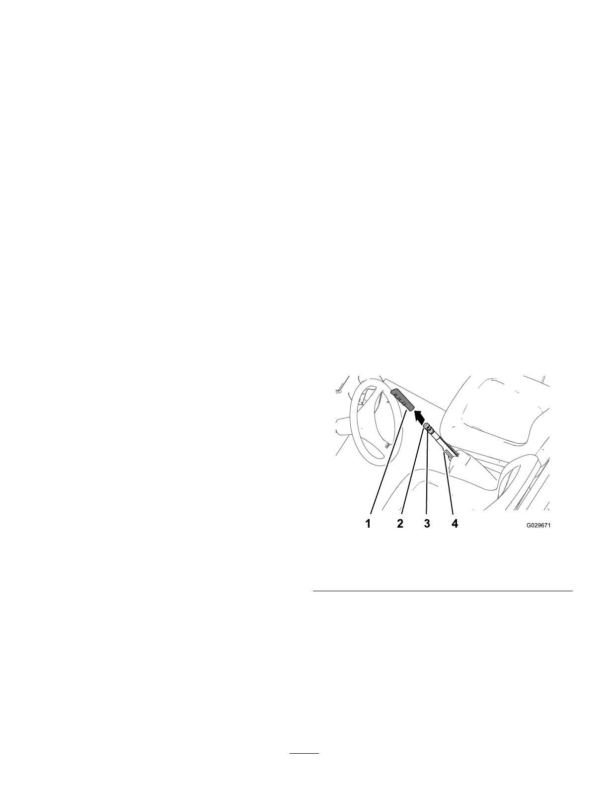
1. Remove the handgrip from the parking-brake
lever ( Figure 62 ).
g029671
Figure 62
1. Handgrip
3. Set screw
2. Brake-adjustment knob 4. Parking-brake lever
2. Loosen the set screw securing the
brake-adjustment knob to the parking-brake
lever ( Figure 62 ).
3. Rotate the brake-adjustment knob until you
reach a force of 133 to 156 N (30 to 35 lbf) to
engage the parking-brake lever ( Figure 62 ).
Note: If you rotated the brake-adjustment knob
the full travel of the adjuster , and cannot attain
the force of 133 to 156 N (30 to 35 lbf) required
to engage the parking-brake lever , perform the
50

 Loading...