35
4400 Series Installation and Operation Manual – 64527-008
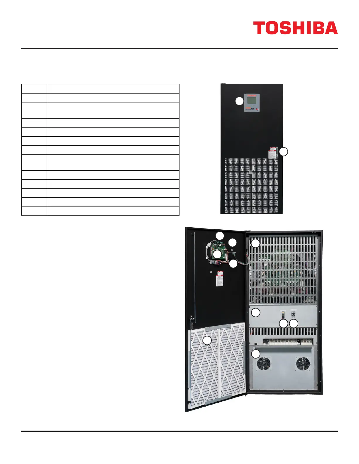
TABLE 8.4: 50KVA UPS COMPONENT LOCATION AND IDENTIFICATION
No. Description
1 Front Panel Display
2 Locking Door Latch with optional Lockout/Ta-
gout Hasp
3 Upper Deadfront
4 Middle Deadfront
5 Lower Deadfront
6 MCCB1 – Primary Input Circuit Breaker
7 MCCB2 Secondary Input Circuit Breaker (Dual
Input)
8 (Optional) Air lter
9 PCB 9 – Display Control Board
10 RemotEye Control Board – PCB-9B
11 RS-232 Plug
12 Dry Contact Connector Plug
8.8
The following table identies the major components of the UPS.
1
2
8
10
9
11
12
7
4
6
5
3
 Loading...