87
4400 Series Installation and Operation Manual – 64527-008
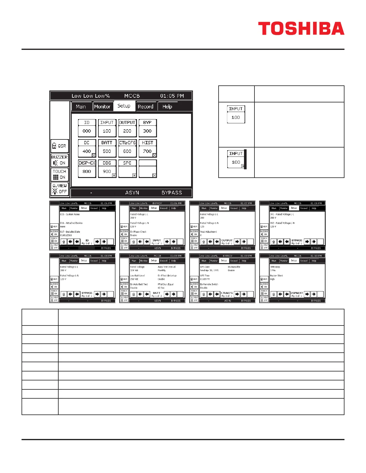
12.16 Tab: Setup
The SETUP tab allows the user to adjust certain UPS parameters. The setup tab shows 12 buttons. Inactive buttons are
indicated with a “x” in the lower right-hand corner of the button. The table below, right, shows a typical SETUP button.
Typical
Button
Signicance
No “x” in the lower right corner
indicates the button is active.
Pressing the button will open
a data page displaying the
parameters available at the
current security level.
A button that has an “x” in the
lower right corner is inactive
and cannot be accessed at the
current security level.
Param.
Parameter Category
0 UPS Identication, Serial number, Start-up Date, software version
1 Input line-line and line-neutral V/I values, V/I percent of rated value, and frequency
2 Output line-line and line-neutral V/I values, V/I percent of rated value, and frequency
3 Bypass line-line and line-neutral V/I values, V/I percent of rated value, and frequency
4 DC Bus Voltage, DC Under Voltage Level, Startup Voltage Level
5 Battery Voltage/Current, shutdown voltage, battery test enable
6 Control and Conguration – UPS time/date/status, faults, warnings, password management
7 UPS Operation time, Number of Faults, Backup, Operations.
8 Display and Ext Comm. – Disp. S/W version, buzzer status, display calibration values.
RemotEye I/P address, data and network status.
FIGURE 12.14: PARAMETER CATEGORIES
SETUP
4400 Series UPS
ASYN ASYN
 Loading...