EasyManua.ls Logo

Toshiba 4400 Series User Manual

Toshiba 4400 Series
138 pages
To Next Page IconTo Next Page
To Previous Page IconTo Previous Page
Page #95 background imageLoading...
Page #95 background image
85
4400 Series Installation and Operation Manual – 64527-008
12.15 Tab: Monitor
The MONITOR tab allows the user to select a specic group of performance parameters to view; Input, Output, Bypass,
DC Link, ID, Control and Conguration, History, and Display and External Communications (RemotEye).
The right side of the display is a vertical stack of ve buttons: 4 active and 1 reserved for future use.
The middle of the display contains ve buttons arranged in a diagram representing the functional model of the UPS. The
lines connecting the mimic buttons represent the power ow from input to output. A thin line indicates no current ow, and
a thick or bold line indicates current ow. See the Mimic Display current Flow Indicator illustration on the following page.
The gure below illustrates the data displayed when the corresponding button is pressed.
MONITOR TAB
FIGURE 12.12: MONITOR TAB DISPLAY OPTIONS
4400F3F050
4400F Series UPS

Table of Contents

Other manuals for Toshiba 4400 Series

Question and Answer IconNeed help?

Do you have a question about the Toshiba 4400 Series and is the answer not in the manual?

Toshiba 4400 Series Specifications

General IconGeneral
BrandToshiba
Model4400 Series
CategoryUPS
LanguageEnglish

Summary

Product Use and Safety

Qualified Personnel

Defines requirements for safe installation, operation, and maintenance.

General Safety Instructions

Explains safety symbols, signal words, and general precautions.

Important Safety Instructions

Critical warnings and guidelines for safe operation.

Warning Labels

Identifies and explains critical safety labels found on the UPS.

Installation and Environment

Unpacking and Inspection

Procedures for receiving, unpacking, and inspecting the UPS.

Storage and Operating Environment

Conditions for optimal performance and longevity.

Installation Safety

Precautions during the installation process.

UPS Anchorage and Clearance

Securing the unit and ensuring proper airflow for ventilation.

UPS Wiring and Electrical Connections

UPS Wiring Safety

Essential safety practices for electrical connections and wiring.

One-Line Diagrams

Schematics illustrating system configurations and power flow.

Power Terminal Blocks and Cable Sizing

Technical guide for connecting power cables and selecting wire sizes.

External Breakers and Grounding

Protection requirements and safety for grounding.

Specifications and Performance

General Specifications

Technical details for 15-30kVA models with internal battery/MBS.

Estimated Runtime on Internal Batteries

Performance data for battery backup duration.

Efficiency and Thermal Loss

Performance metrics related to power conversion.

50kVA and 80-100kVA Specifications

Details for larger capacity models.

Operator Interface and Operation

Operator Controls Overview

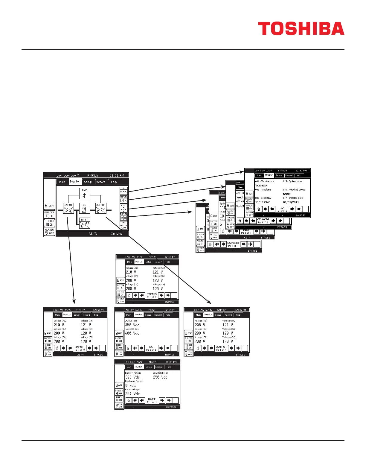
Description of physical controls and the UPS display panel.

Touch Screen Navigation

How to navigate and use the display interface.

UPS Modes and Operation

Understanding operational states and basic startup procedures.

Battery Management

Understanding battery performance, charging, and low voltage conditions.

Options and Physical Dimensions

Available Options

Overview of optional features and accessories.

External Layouts and Dimensions

Physical size, weight, and clearance information.

Dimensional Drawings (Appendix A)

Visual representations of physical dimensions.

Related product manuals