56
4400 Series Installation and Operation Manual – 64527-008
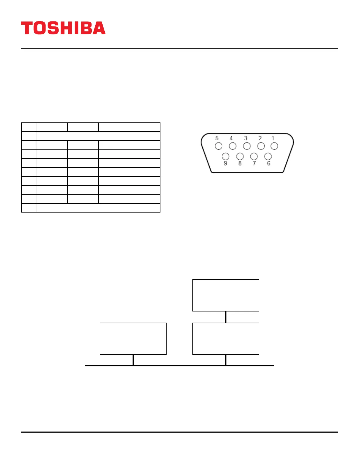
10.3 RS-232C
The RS-232C port just to the right of the display PCB can be used by authorized service personnel. The port is provided
using a DB9 female connector located to on the inside of the UPS door just to the right of the Display PCB. For reference,
the pinout of the connector is illustrated below.
NOTE: Use the cross cable provided by Toshiba to avoid potential communications problems.
RS-232C CONNECTOR PIN ASSIGNMENT DB9 FEMALE CONNECTOR OUTLINE
(FACING CONNECTOR)
Pin I/O Symbol Description
1 This pin is not used
2 Input RXD Receive data
3 Output TXD Transmit data
4 Output DTR Data Terminal Ready
5 - SG Signal ground
6 Input DSR Data Set Ready
7 Output RTS Request to Send
8 Input CTS Clear to Send
9 This pin is not used
FIGURE 10.2: RS-232C INTERFACE
10.4 RemotEye Network Card
The optional RemotEye network card for the Toshiba UPS permits network monitoring and control of the UPS. This card is
located on the back side of the UPS door next to DB9. The card provides a network, or LAN-based communication interface
for the UPS. When installed, the UPS can be managed remotely using the common SNMP, HTTP , BACnet, or Modbus
RS-232/RS-485 or web-based network protocols. The following diagram shows the ow of the Network Management
Station.
NETWORK BACKBONE
NETWORK MANAGEMENT
STATION OR PC WITH
WEB BROWSER
REMOTEYE NETWORK
CARD
TOSHIBA UPS
FIGURE 10.3 – NETWORK INTERFACE
 Loading...