 Loading...
Do you have a question about the Toshiba e-STUDIO453 and is the answer not in the manual?
| Brand | Toshiba |
|---|---|
| Model | e-STUDIO453 |
| Category | All in One Printer |
| Language | English |
Guidelines for safely moving and setting up the equipment.
Precautions and safety measures to take when servicing the machine.
Highlights critical components for safe operation and maintenance.
Information regarding important safety labels on the equipment.
Guidance on proper disposal of materials according to regulations.
Procedures to prevent damage to electronic components from static discharge.
Details on the technical features and capabilities of the equipment.
Lists the items included with the equipment.
Lists optional components and add-ons for the equipment.
Information on consumable items like toner and developer.
Explains the internal structure of the machine with diagrams.
Illustrates the arrangement of electrical components within the machine.
Details the purpose and symbols of different parts within the machine.
Instructions for removing and installing external covers and circuit boards.
Outlines the step-by-step process of how copying is performed.
Provides in-depth explanations of each stage in the copying process.
General guide to operating the equipment.
Detailed explanation of how to perform various operations.
Information on how the machine detects and reports errors.
Description of the control panel layout and its display elements.
Explains the various information displayed on the equipment's screen.
Detailed explanation of how the equipment operates.
Explains the purpose and basic operation of the scanner.
Details the physical components and structure of the scanner.
Explains how the scanner functions during operation.
Instructions for removing and installing scanner components.
Overview of the image processing stages.
Details the functions and features of the SLG board.
Details the functions and features of the LGC board.
Explains the function of the LDR board in laser control.
Overview of the laser optical system.
Describes the physical construction of the laser optical unit.
Details the laser diode, its specifications, and control.
Explains the polygonal motor's drive circuit and control signals.
Describes the purpose and main components of the paper feeding system.
Explains how the paper feeding system operates.
Instructions for disassembling and replacing components in the paper feeding system.
Overview of the machine's drive system and main motor.
Details the main motor's drive and control signals.
Instructions for removing and replacing drive system components.
Outlines the components around the drum and their arrangement.
Explains the roles of the drum and related components.
Details the circuits controlling high voltage outputs for chargers and bias.
Instructions for removing and replacing drum-related parts.
Describes the components of the development system.
Explains the functions of the toner cartridge and developer unit.
Explains the circuit that manages toner density and supply.
Instructions for disassembling and replacing developer system components.
Overview of the fuser unit and its role in fusing toner.
Explains how the fuser unit operates to fuse toner onto paper.
Details the functions of the IH coil, rollers, and thermistors.
Describes the circuit that controls the heating elements.
Instructions for disassembling and replacing fuser unit components.
Overview of the ADU's function in duplex printing.
Explains the operational procedures for duplex printing.
Instructions for disassembling and replacing ADU components.
Describes the construction of the power supply unit, including AC filter and DC outputs.
Explains the sequence of power supply output during startup and shutdown.
Information on fuses and troubleshooting related to blown fuses.
Timing chart illustrating the power supply sequence.
Diagram and identification of the main system PC board.
Diagram and identification of the LGC PC board.
Diagram and identification of the SLG PC board.
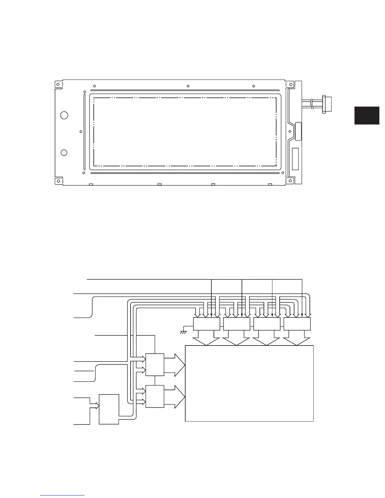
Diagram and identification of the CCD PC board.
Diagram and identification of the LRL PC board.
Diagram and identification of the LDR PC board.
Diagram and identification of the SNS PC board.
Diagram and identification of the ADU PC board.
Diagram and identification of the DSP PC board.
Diagram and identification of the KEY PC board.
Diagram and identification of the FIL PC board.
Diagram and identification of the FUS PC board.