EasyManuals Logo

Toshiba e-STUDIO453 User Manual

Toshiba e-STUDIO453
302 pages
To Next Page IconTo Next Page
To Previous Page IconTo Previous Page
Page #175 background imageLoading...
Page #175 background image
e-STUDIO350/352/353/450/452/453
PAPER FEEDING SYSTEM
9
9 - 9
© 2003 - 2008 TOSHIBA TEC CORPORATION All rights reserved
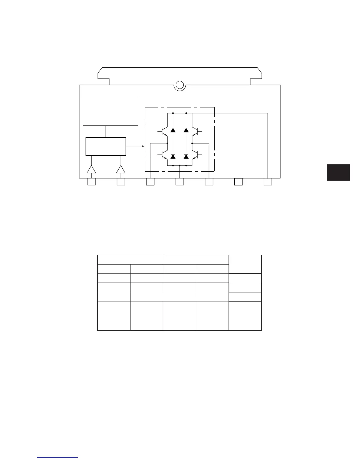
9.3 Drive Circuit of Tray-up Motor
The tray-up motor (T-UP-MTR) is driven by the LGC board IC1 (LGC: TA8428). The block diagram of
TA8428 is shown below.
IN1 and IN2 are input terminals to receive the signals from the tray-up motor. The control logic based
on the signals from the tray-up motor, controls ON/OFF of the rotation direction.
IN1
H
L
H
L
IN2
H
H
L
L
M (+)
L
L
H
OFF
(high im
-
pedance)
M (–)
L
H
L
State
Brake
CCW
CW
Stop
Input Output
Fig. 9-301
1 2 3 4 5 6 7
IN1 IN2 M(+) GND M(-) N.C. VCC
Thermal shutdown
over-current
protection circuit
Control logic

Table of Contents

Questions and Answers:

Question and Answer IconNeed help?

Do you have a question about the Toshiba e-STUDIO453 and is the answer not in the manual?

Toshiba e-STUDIO453 Specifications

General IconGeneral
BrandToshiba
Modele-STUDIO453
CategoryAll in One Printer
LanguageEnglish

Related product manuals