RT-SVX060D-GB
19
11UNT-PRC002-GB
Sound power levels
Discharge
Measurement conditions:
Measurements taken in a room adjacent to the room containing the FWD, at the outlet of the rectangular duct (1.5 m
long) fixed to its discharge opening.
Fan Power level in dB(A), per Hz frequency band Overall power
Unit speed 125 250 500 1000 2000 4000 8000 dB(A)
1 55 50 42 37 37 31 30 46
FWD 08 2 57 54 47 40 30 38 40 50
3 58 57 50 42 32 40 43 53
1 57 51 45 42 34 33 28 48
FWD 10 2 58 54 48 45 38 39 35 51
3 60 58 50 48 40 42 39 54
1 57 51 45 42 34 33 28 48
FWD 12 2 58 54 48 45 38 39 35 51
3 60 58 50 48 40 42 39 54
1 56 62 50 48 39 38 36 56
FWD 14 2 61 66 55 53 47 46 45 60
3 63 69 58 56 50 50 49 63
1 57 63 51 49 40 39 37 57
FWD 20 2 61 66 55 53 47 46 45 60
3 63 69 58 56 50 50 49 63
Intake
Measurement conditions:
Measurements taken at the horizontal air intake.
Fan Power level in dB(A), per Hz frequency band Overall power
Unit speed 125 250 500 1000 2000 4000 8000 dB(A)
1 56 55 55 53 46 45 42 57
FWD 08 2 63 62 60 60 53 53 53 64
3 66 65 63 62 56 55 57 67
1 62 58 55 58 51 48 44 61
FWD 10 2 66 63 60 62 56 55 52 66
3 70 67 63 65 59 59 57 69
1 62 58 55 58 51 48 44 61
FWD 12 2 66 63 60 62 56 55 52 66
3 70 67 63 65 59 59 57 69
1 66 65 65 65 57 50 46 68
FWD 14 2 73 72 69 71 64 59 57 74
3 78 76 73 75 69 64 63 78
1 68 72 64 64 56 52 50 69
FWD 20 2 76 76 68 71 65 61 61 75
3 78 79 71 74 69 66 66 78
Installation
Instructions for the roofcurb assembly and installation
In order to insure watertighness of the roofcurb
assembly, it is important to respect the schematics
below and to consult the booklet for roofcurb assembly
shipped with the roofcurb module. Be sure that gasket is
positioned on the roofcurb and without damage before
unit positioning.
To avoid any property damage or personal injury, it
is the installer’s responsibility to make sure that the
installation will not impair the function of this curb, or
the unit to be installed; and that the roofcurb and unit
must be completely sealed, preventing any water or air
leakage damage.
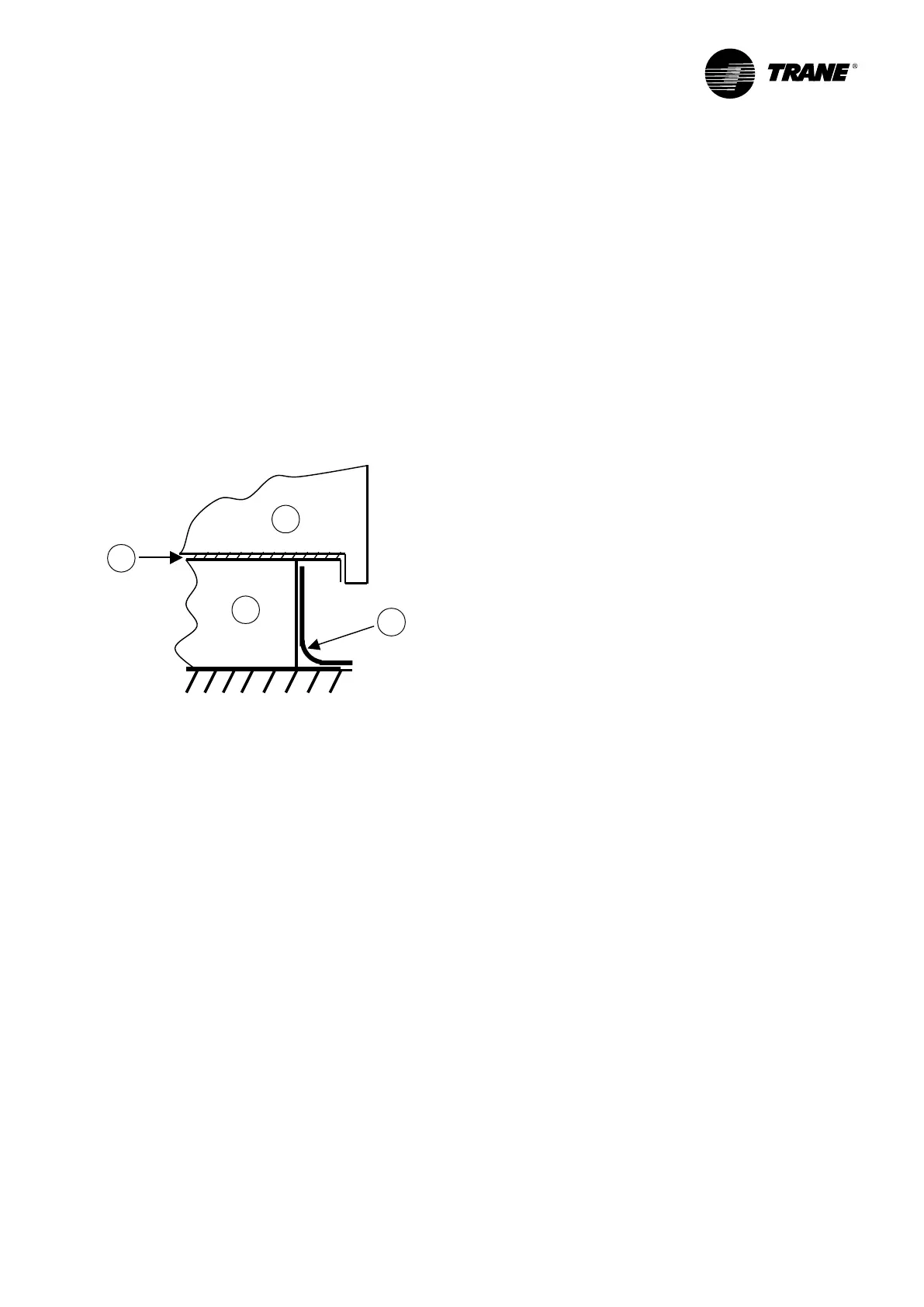
Figure 3 - Waterproong
1
2
3
4
1. Roofcurb
2. Roof membrane
3. Seal
4. Rooftop
Installing the Unit
The structure accommodating the unit(s) must be
designed to support the equipment in operation, as
a minimum. Refer to submittals drawings supplied
with the unit for dimensions, weight and clearance
requirement around unit.
Unit support
Install the unit on a at foundation strong enough to
support unit loading and level (within 5 mm across
the length and width of the unit).If the unit is to be
roof mounted check the building codes for weight
distribution requirements
Location and clearances
Choose a location that will enable air to circulate
freely in the condenser coil and allow air to be
discharged above the fans. The clearance distances
for air circulation and maintenance are indicated in
the submittals drawings.
Placing and rigging
The rooftop units are designed to be installed outdoor
and must be positioned horizontally (vertical air
discharge off the condenser).
Slab mount
For ground level installation, the unit base should be
adequately supported and hold the unit near level.
In areas where snowfall is common, the unit must
be elevated enough to ensure that the bottom of the
outdoor coil is above the height of the expected snow
accumulation.
Where severely cold temperatures are a consideration,
elevation of the unit is again recommended to ensure
that defrost water does not create an ice build up that
will interfere with unit operation. In addition, runoff
water from roofs, etc... must not be allowed to fall on
the outdoor coil; any blockage of airow through the
coil can be detrimental to unit operation and reliability.
The manufacturer suggests that the bottom of the
outdoor coil be raised 30cm above grade or roof to
prevent possible ice build-up problems.
The unit frame structure is not designed to be supported
by four points (mounting on spring isolators for
instance).
The unit must therefore rest on its whole base.
 Loading...
