RT-SVX060D-GB
41
11UNT-PRC002-GB
Sound power levels
Discharge
Measurement conditions:
Measurements taken in a room adjacent to the room containing the FWD, at the outlet of the rectangular duct (1.5 m
long) fixed to its discharge opening.
Fan Power level in dB(A), per Hz frequency band Overall power
Unit speed 125 250 500 1000 2000 4000 8000 dB(A)
1 55 50 42 37 37 31 30 46
FWD 08 2 57 54 47 40 30 38 40 50
3 58 57 50 42 32 40 43 53
1 57 51 45 42 34 33 28 48
FWD 10 2 58 54 48 45 38 39 35 51
3 60 58 50 48 40 42 39 54
1 57 51 45 42 34 33 28 48
FWD 12 2 58 54 48 45 38 39 35 51
3 60 58 50 48 40 42 39 54
1 56 62 50 48 39 38 36 56
FWD 14 2 61 66 55 53 47 46 45 60
3 63 69 58 56 50 50 49 63
1 57 63 51 49 40 39 37 57
FWD 20 2 61 66 55 53 47 46 45 60
3 63 69 58 56 50 50 49 63
Intake
Measurement conditions:
Measurements taken at the horizontal air intake.
Fan Power level in dB(A), per Hz frequency band Overall power
Unit speed 125 250 500 1000 2000 4000 8000 dB(A)
1 56 55 55 53 46 45 42 57
FWD 08 2 63 62 60 60 53 53 53 64
3 66 65 63 62 56 55 57 67
1 62 58 55 58 51 48 44 61
FWD 10 2 66 63 60 62 56 55 52 66
3 70 67 63 65 59 59 57 69
1 62 58 55 58 51 48 44 61
FWD 12 2 66 63 60 62 56 55 52 66
3 70 67 63 65 59 59 57 69
1 66 65 65 65 57 50 46 68
FWD 14 2 73 72 69 71 64 59 57 74
3 78 76 73 75 69 64 63 78
1 68 72 64 64 56 52 50 69
FWD 20 2 76 76 68 71 65 61 61 75
3 78 79 71 74 69 66 66 78
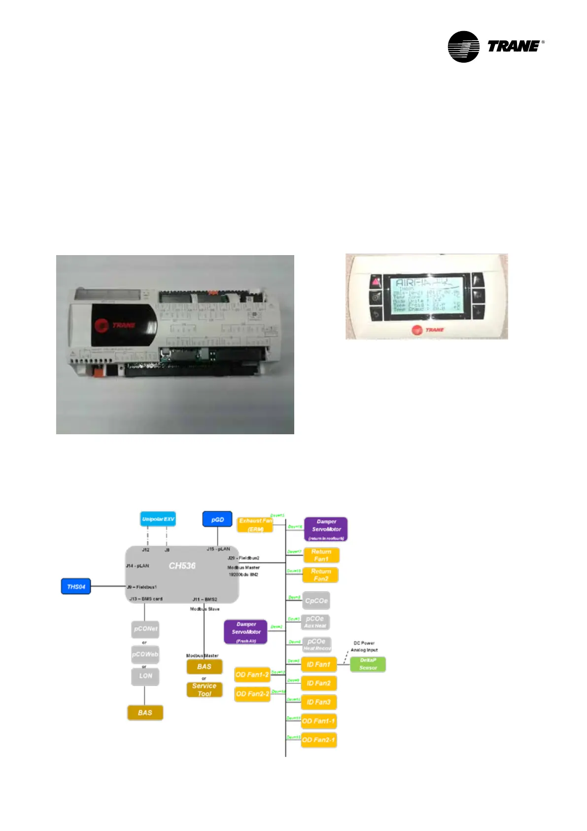
CH536 + module extension
Control Hardware Modules
The main CH536 module allows the control of the heat
pump, the indoor EC fan and the outdoor fan.
3 extension module can be used :
- 1 module for auxiliary heat, economizer enthalpy,
exhaust fan and for ERP.
- 1 module for heat recovery.
- 1 extension module to manage customer options.
Figure 24 - CH536 main module
Control Hardware Bus
This diagram is for information. For details refer to
wiring diagram shipped with the unit.
Figure 25 - Control Hardware Bus
Service Terminal
The service terminal is an option to the customer,
easily plugged to unit through cable. The controller
is composed of six different buttons and a graphical
display. This view of plug-and-play service and the
controller allows personal service to read and modify
some parameters of the device as setpoints (cooling and
heating), airow, alarm and warning display.
It includes scrolling menus and explanation of full text.
Figure 26 - Optional display
Controls
 Loading...
