RT-SVX060D-GB
21
11UNT-PRC002-GB
Sound power levels
Discharge
Measurement conditions:
Measurements taken in a room adjacent to the room containing the FWD, at the outlet of the rectangular duct (1.5 m
long) fixed to its discharge opening.
Fan Power level in dB(A), per Hz frequency band Overall power
Unit speed 125 250 500 1000 2000 4000 8000 dB(A)
1 55 50 42 37 37 31 30 46
FWD 08 2 57 54 47 40 30 38 40 50
3 58 57 50 42 32 40 43 53
1 57 51 45 42 34 33 28 48
FWD 10 2 58 54 48 45 38 39 35 51
3 60 58 50 48 40 42 39 54
1 57 51 45 42 34 33 28 48
FWD 12 2 58 54 48 45 38 39 35 51
3 60 58 50 48 40 42 39 54
1 56 62 50 48 39 38 36 56
FWD 14 2 61 66 55 53 47 46 45 60
3 63 69 58 56 50 50 49 63
1 57 63 51 49 40 39 37 57
FWD 20 2 61 66 55 53 47 46 45 60
3 63 69 58 56 50 50 49 63
Intake
Measurement conditions:
Measurements taken at the horizontal air intake.
Fan Power level in dB(A), per Hz frequency band Overall power
Unit speed 125 250 500 1000 2000 4000 8000 dB(A)
1 56 55 55 53 46 45 42 57
FWD 08 2 63 62 60 60 53 53 53 64
3 66 65 63 62 56 55 57 67
1 62 58 55 58 51 48 44 61
FWD 10 2 66 63 60 62 56 55 52 66
3 70 67 63 65 59 59 57 69
1 62 58 55 58 51 48 44 61
FWD 12 2 66 63 60 62 56 55 52 66
3 70 67 63 65 59 59 57 69
1 66 65 65 65 57 50 46 68
FWD 14 2 73 72 69 71 64 59 57 74
3 78 76 73 75 69 64 63 78
1 68 72 64 64 56 52 50 69
FWD 20 2 76 76 68 71 65 61 61 75
3 78 79 71 74 69 66 66 78
Dimensions/Weights and Clearance
This information is supplied in the document package
shipped with the unit.
Connection of Duct Network
Supply and return openings have curb anges provided
for easy duct installation. It is recommended to insulate
the circumference of the curb after the unit is mounted
to prevent condensation.
CAUTION! All ductwork must be run and attached to the
curb anges before the unit is set into place.
Guidelines for ductwork construction
- Connections to the unit should be made with 7.5 cm
canvas connectors to minimize noise and vibration
transmission.
- Elbows with turning vanes or splitters recommended
to minimize air noise and resistance.
- The rst elbow in the ductwork leaving the unit should
be no closer than 60 cm from the unit, to minimize
noise and resistance.
Attaching horizontal ductwork to unit
- All conditioned air ductwork should be insulated
to minimize heating and cooling duct losses. Use a
minimum of 5 cm of insulation with a vapour barrier.
The outside ductwork must be waterproof between
the unit and the building.
- When attaching ductwork to a horizontal unit, provide
a exible watertight connection to prevent noise
transmission from the unit to the duct. The exible
connection must be indoors and made out of heavy
canvas.
Note: Do not draw the canvas taut between the solid
ducts.
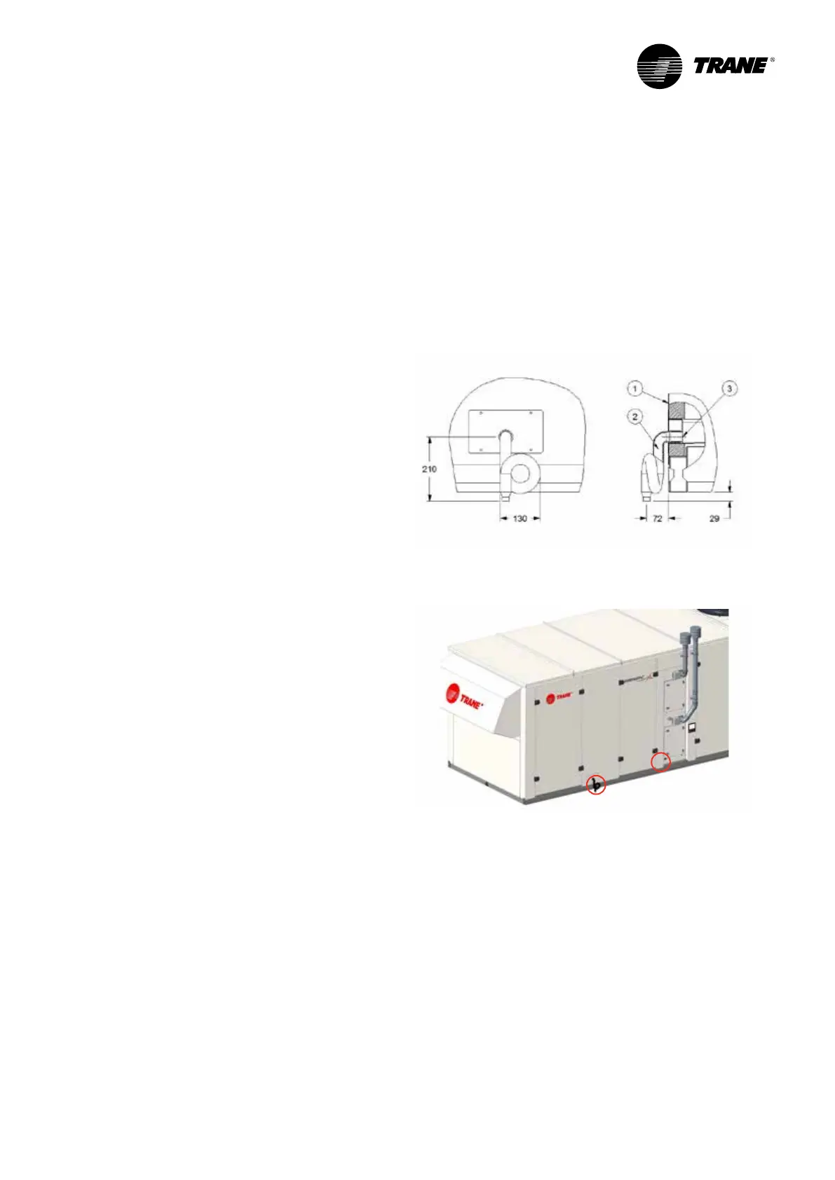
Condensate Drain Piping
Each unit is equipped with a 1 1/4” female drainage
connector. A P trap is supplied and must be connected
to the drainage as shown in Figure 5.
Slope the drainage pipe down at least 1% to ensure an
adequate condensate ow.
Check all the condensate drainage pipe ttings comply
with the applicable construction regulations and waste
disposal standards.
Figure 6 - Supplied trap installation
Figure 7 - Drain piping location
1: Removable unit drain pan
2: Gas burner drain pan
1
2
Installation
 Loading...
