RT-SVX060D-GB
25
11UNT-PRC002-GB
Sound power levels
Discharge
Measurement conditions:
Measurements taken in a room adjacent to the room containing the FWD, at the outlet of the rectangular duct (1.5 m
long) fixed to its discharge opening.
Fan Power level in dB(A), per Hz frequency band Overall power
Unit speed 125 250 500 1000 2000 4000 8000 dB(A)
1 55 50 42 37 37 31 30 46
FWD 08 2 57 54 47 40 30 38 40 50
3 58 57 50 42 32 40 43 53
1 57 51 45 42 34 33 28 48
FWD 10 2 58 54 48 45 38 39 35 51
3 60 58 50 48 40 42 39 54
1 57 51 45 42 34 33 28 48
FWD 12 2 58 54 48 45 38 39 35 51
3 60 58 50 48 40 42 39 54
1 56 62 50 48 39 38 36 56
FWD 14 2 61 66 55 53 47 46 45 60
3 63 69 58 56 50 50 49 63
1 57 63 51 49 40 39 37 57
FWD 20 2 61 66 55 53 47 46 45 60
3 63 69 58 56 50 50 49 63
Intake
Measurement conditions:
Measurements taken at the horizontal air intake.
Fan Power level in dB(A), per Hz frequency band Overall power
Unit speed 125 250 500 1000 2000 4000 8000 dB(A)
1 56 55 55 53 46 45 42 57
FWD 08 2 63 62 60 60 53 53 53 64
3 66 65 63 62 56 55 57 67
1 62 58 55 58 51 48 44 61
FWD 10 2 66 63 60 62 56 55 52 66
3 70 67 63 65 59 59 57 69
1 62 58 55 58 51 48 44 61
FWD 12 2 66 63 60 62 56 55 52 66
3 70 67 63 65 59 59 57 69
1 66 65 65 65 57 50 46 68
FWD 14 2 73 72 69 71 64 59 57 74
3 78 76 73 75 69 64 63 78
1 68 72 64 64 56 52 50 69
FWD 20 2 76 76 68 71 65 61 61 75
3 78 79 71 74 69 66 66 78
General Electrical Recommendations
Electrical Parts
When reviewing this manual keep in mind.
- All eld-installed wiring must be in accordance with
local regulations, CE directives and guidelines. Be sure
to satisfy proper equipment grounding requirements
according CE.
- The following standardized values - Maximum Amps -
Short Circuit Amps - Starting Amps are displayed on
unit nameplate.
- All eld-installed wiring must be checked for proper
terminations, and for possible shorts or grounds.
Note: always refer to wiring diagrams shipped with unit
or unit submittal for specic electrical schematic and
connection information.
WARNING Hazardous Voltage!
Disconnect all electric power, including remote
disconnects before servicing. Follow proper lockout/
tagout procedures to ensure the power can not be
inadvertently energized. Failure to disconnect power
before servicing could result in death or serious injury.
Important!
Do not allow conduit to interfere with other
components, structural members or equipment. Control
voltage (230 V) wiring in conduit must be separate from
conduit carrying low voltage (<30V) wiring. To prevent
control malfunctions, do not run low voltage wiring
(<30V) in conduit with conductors carrying more than
30 volts.
CAUTION!
Inverters are equipped with integrated lters.
They are not compatible with insulated neutral load
earthing arrangements.
WARNING! High voltage!
Any contact with electric components , even after the
unit has been switched off, can cause serious injury or
death. Wait at least 5 minutes after switching off the
unit, until the current dissipates.
Installer-Supplied Components
Customer wiring interface connections are shown in the
electrical schematics and connection diagrams that are
shipped with the unit. The installer must provide the
following components if not ordered with the unit:
• Power supply wiring (in conduit) for all eld-wired
connections.
• All control (interconnecting) wiring (in conduit) for
eld supplied devices.
• Circuit breakers.
Grounding
Be sure to ground the unit and differential protection
should be suited for industrial machinery with current
leak which can be higher than 300 mA (several motors
and frequency drives).
CAUTION!
To avoid corrosion, overheating or general damage,
at terminal connections of power supply wiring, unit
is designed for copper mono-conductors only. In case
of multiconductor cable, an intermediate connection
box must be added. For cable with alternative material,
bi-material connecting devices are mandatory. Cable
routing inside control panel should be made case by
case by installer.
WARNING Ground Wire!
All eld-installed wiring must be completed by qualied
personnel. All eld-installed wiring must comply with
local codes and regulations. Failure to follow this
instruction could result in death or serious injury.
All power supply wiring must be sized and selected
accordingly by the project engineer in accordance with
local codes and regulations.
WARNING!
The Warning Label which is displayed on the equipment
and shown on wiring diagrams and schematics. Strict
adherence to these warnings must be observed. Failure
to do so may result in personal injury or death.
CAUTION!
Units must not be linked to the neutral wiring of the
installation. Units are compatible with the following
neutral operating conditions:
TNS IT TNC TT
Standard** Special Special Standard*
* Differential protection should be suited for industrial
machinery with current leak which can be higher than
300 mA (several motors and frequency drives).
Neutral wire not distributed.
** Neutral wire not distributed
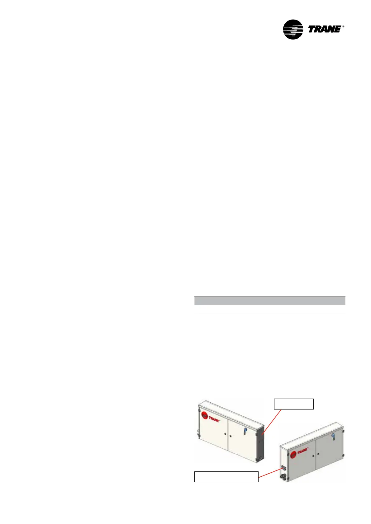
Electrical Connections
The electric panel is located on the length of the indoor
section behind the plug fan section. The unit is designed
to run with 400V (+/-10%) - 50 Hz (+/-1%) - 3 ph.
Power supply
4 cables glands for control
Installation
 Loading...
