RT-SVX060D-GB
38
4 UNT-PRC002-GB
Technical Data
FWD 08 12 20 30 45
Power supply (V/Ph/Hz) 230/1/50
Capacities
Cooling capacity on water (1) (kW) 5,2 8,3 15 18,8 30,1
Heating capacity on water (2) (kW) 6,3 11,9 18,9 20,9 38,2
Fan motor (type) 2 x direct drive centrifugal
Fan power input (3) (kW) 0,23 0,46 0,65 1,04 1,51
Current amps (3) (A) 1,1 2,2 3,1 4,7 5,5
Start-up amps (A) 3,2 5,5 9,3 14,1 16,5
Air flow
minimum (m
3
/h) 490 980 1400 1800 2700
nominal (m
3
/h) 820 1650 2300 3000 4500
maximum (m
3
/h) 980 1970 2600 3600 5400
Main coil
Water entering/leaving connections (type) ISO R7 rotating female
(Dia) 3/4" 3/4" 1 1/2" 1 1/2" 1 1/2"
Electric heater (accessory for blower only)
Electric power supply (V/Ph/Hz) 230/1/50 230/1/50 or 400/3/50 400/3/50 400/3/50 400/3/50
Heating capacity (kW) 2/4 8 10 12 12
Hot water coil (accessory for blower only)
Heating capacity (4) (kW) 6,3 12 17,4 22,4 34,5
G2 filter (filter box accessory)
Quantity 2 2 2 2 2
Dimensions ( LxWxth) (mm) 386x221x8 486x271x8 586x321x8 586*421*8 586*621*8
G4 filter (filter box accessory)
Quantity - 2 2 2 2
Dimensions ( LxWxth) (mm) - 486x264x48 586x314x48 586*414*48 586*614*48
Condensate pump (accessory) (type) Centrifugal
Water flow - lift height (l/h - mm) 24 - 500
Not available for FWD30 and FWD45
Sound level (L/M/H speed)
Sound pressure level (5) (dB(A)) 36/40/43 38/41/44 46/50/53 47/52/57 47/52/58
Sound power level (5) (dB(A)) 46/50/53 48/51/54 56/60/63 57/62/67 57/62/68
Unit dimensions
Width x Depth (mm) 890 x 600 1090 x 710 1290 x 820 1290 x 970 1290 x 1090
Height (mm) 250 300 350 450 650
Shipped unit dimensions
Width x Depth (mm) 933 x 644 1133 x 754 1333 x 864 1333 x 1008 1333*1133
Height (mm) 260 310 360 460 660
Weight (kg) 32 46 61 76 118
Colour galvanised steel
Recommended fuse size
Unit alone (aM/gI) (A) 8/16 8/16 8/16 8/25 8/25
Unit with electric heater (gI) (A) 16 (2kW),25 (4kW) 40 (230V),3*16 (400V) 3*20 3*25 3*25
(1) Conditions: Water entering/leaving temperature: 7/12 °C, Air inlet temperature 27/19°C DB/WB - Nominal air flow
(2) Conditions: Water entering/leaving temperature: 50/45 °C, Air inlet temperature 20°C DB - Nominal air flow
(3) At high speed with nominal air flow.
(4) Water entering/leaving temperature 90/70 °C, air inlet temperature 20 °C DB, Nominal air flow.
(5) A rectangular glass wool duct 1m50 long is placed on the blower.The measurement is taken in the room containing the blower unit.
Heat exchanger operating limits:
FWD:
*water temperature: max 100° C
*absolute service pressure: min 1 bar/max 11 bars
Accessories - Hot water coil:
*water temperature: min. +2° C/max. 100° C
*absolute service pressure: min 1 bar/max 11 bars
Exhaust Fans
The exhaust plug fans EC are used to minimize the
overpressure in the building caused by the introduction
of fresh air.
This option is typically used when the fresh air intake
needed is between 40 to 50% of the nominal air ow or
when the return air duct pressure drop is higher than
25Pa (<70Pa or 150Pa according to option selected).
This option includes hoods, gravity dampers and axial
fans.
Optional service Terminal allow to adjust exhaust fans
EC start and stop value according to fresh air damper
position.
When the supply air fan is ON, the exhaust fans EC
turn on whenever the position of the fresh air dampers
meet or exceed the exhaust fan EC set point. (If the
potentiometer is set at 40%, the exhaust fans EC will
start when the fresh air dampers will meet or exceed
40% opening).
Operation
• When the exhaust fans EC are OFF :
- The barometric dampers open when the air pressure
inside the building increases.
As the building pressure increases, the pressure in
the unit return section also increases, opening the
dampers and relieving the air.
- If return air pressure drop>building overpressure
(∆P>Pb – Patm) → barometric damper is closed.
- If return air pressure drop<building overpressure
(∆P< Pb – Patm) → barometric damper opens and
a maximum of 25% of the nominal airow can be
exhausted.
• When the exhaust fans EC turn ON :
- Around 50% of airow can be exhausted, depending
on the pressure drop in the return air duct.
- The two fans work always together, on stage ON-OFF.
- Each fan has two speeds, which makes 2 congurable
speeds by changing the wiring on site.
- The exhaust fan EC is started when fresh air dampers
meet or exceed a preset percentage of fresh air.
Congured for Return roofcurb (ESP=250 PA)
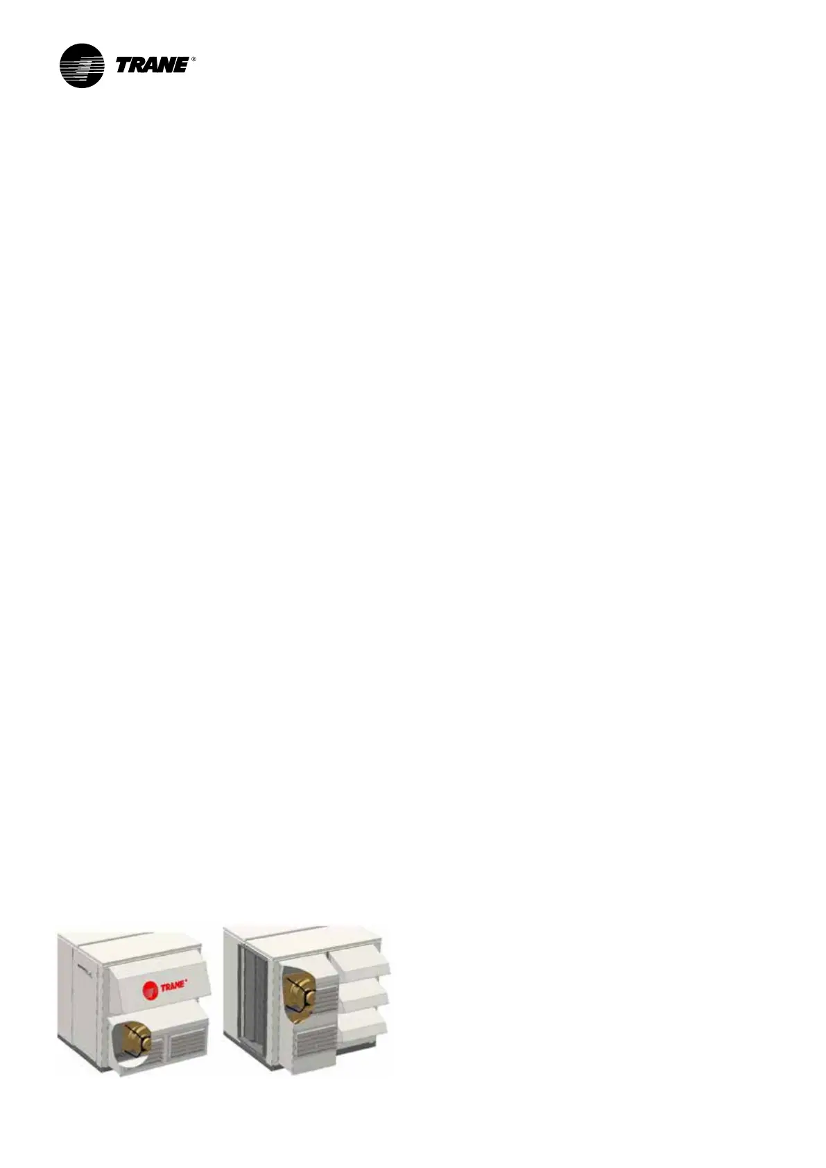
Figure 15 - Exhaust fan
Options
 Loading...
