RT-SVX060D-GB
47
11UNT-PRC002-GB
Sound power levels
Discharge
Measurement conditions:
Measurements taken in a room adjacent to the room containing the FWD, at the outlet of the rectangular duct (1.5 m
long) fixed to its discharge opening.
Fan Power level in dB(A), per Hz frequency band Overall power
Unit speed 125 250 500 1000 2000 4000 8000 dB(A)
1 55 50 42 37 37 31 30 46
FWD 08 2 57 54 47 40 30 38 40 50
3 58 57 50 42 32 40 43 53
1 57 51 45 42 34 33 28 48
FWD 10 2 58 54 48 45 38 39 35 51
3 60 58 50 48 40 42 39 54
1 57 51 45 42 34 33 28 48
FWD 12 2 58 54 48 45 38 39 35 51
3 60 58 50 48 40 42 39 54
1 56 62 50 48 39 38 36 56
FWD 14 2 61 66 55 53 47 46 45 60
3 63 69 58 56 50 50 49 63
1 57 63 51 49 40 39 37 57
FWD 20 2 61 66 55 53 47 46 45 60
3 63 69 58 56 50 50 49 63
Intake
Measurement conditions:
Measurements taken at the horizontal air intake.
Fan Power level in dB(A), per Hz frequency band Overall power
Unit speed 125 250 500 1000 2000 4000 8000 dB(A)
1 56 55 55 53 46 45 42 57
FWD 08 2 63 62 60 60 53 53 53 64
3 66 65 63 62 56 55 57 67
1 62 58 55 58 51 48 44 61
FWD 10 2 66 63 60 62 56 55 52 66
3 70 67 63 65 59 59 57 69
1 62 58 55 58 51 48 44 61
FWD 12 2 66 63 60 62 56 55 52 66
3 70 67 63 65 59 59 57 69
1 66 65 65 65 57 50 46 68
FWD 14 2 73 72 69 71 64 59 57 74
3 78 76 73 75 69 64 63 78
1 68 72 64 64 56 52 50 69
FWD 20 2 76 76 68 71 65 61 61 75
3 78 79 71 74 69 66 66 78
Operation
Gas Burner rst start
The PCH burners are supplied with factory settings
according to model number gas selection. They are
tested for the gas specied on the burner nameplate.
However it is required to
- Check the gas category
- Check the gas intake pressure on the gas valve
- Perform the combustion analysis to verify
that the level of ue gases corresponds to
the data contained in general data table or in
manufacturer IOM manual.
When turned on for the rst time, the pilot burner may
not ignite due to air kept in gas hose. There is the need
to reset the equipment and repeat the operation until
gas hose is purged and it ignites.
Consult electrical drawing and supplier IOM shipped
with the unit.
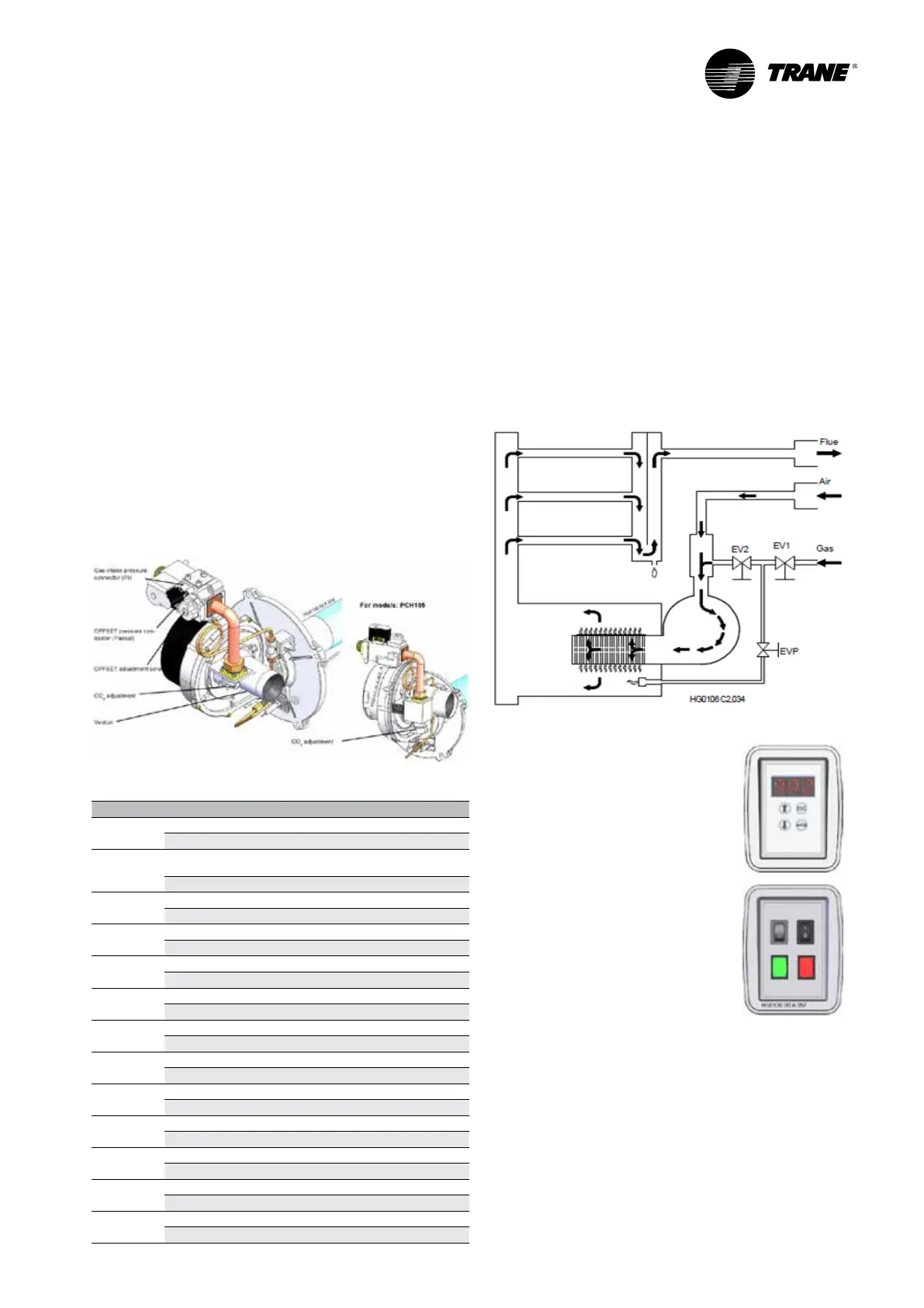
Figure 27 - Example of PCH burner
Table 2 - Marking Category of gas section in different countries
CATEGORY G20 G25 G31
II
2Esi3P
FR
mbar 20 25 37
II
2H3B/P
DK, FI, GR, SE, NO, IT, CZ, EE, LT, SI, AL, MK,
BG, RO, HR, TR
mbar 20 - 30
II
2H3B/P
AT, CH
mbar 20 - 50
II
2HS3B/P
HU
mbar 25 - -
II
2L3B/P
NL
mbar - 25 30/37/50
II
2H3P
ES, GB, IE, PT, SK
mbar 20 - 37
I
2E( S )
BE < 70kW
mbar 20 25 -
I
2E( R )
BE > 70kW
mbar 20 25 -
II
2ELwLs3B/P
PL
mbar 20 - 37
II
2E3P
LU
mbar 20 - 30/37/50
II
2ELL3B/P
DE
mbar 20 20 50
I
3P
BE
mbar - - 37
I
2H
LV
mbar 20 - -
Premix burner working cycle
1. Heat request signal coming from CH536
2. Burner fan starts to pre-wash combustion chamber
3. EV1 and EVP gas valves open to allow gas to feed
pilot burner
4. Start up electrode gives ignition sparks on pilot
burner
5. EV2 main gas valve opens to gas feed main burner
6. Combustion starts thanks to pilot ame ignition
7. Pilot and main burners work together for a shor time,
then the electronic boards close EVP and stops the
pilot
Figure 28 - Premix burner of working cycle
Interface panel
PCH
Red 3 digit LCD display
Module status (rdy, On, Off, Fxx...)
3 levels menu:
- I/O (Input/Output)
- PAR (parameters)
- Flt (Faults)
PRH
Green light : power supply
red lights : faults - diagnostics
available by pressing button for
more than 5 sec.
Reset button
Summer/winter button
 Loading...
