RT-SVX060D-GB
23
11UNT-PRC002-GB
Sound power levels
Discharge
Measurement conditions:
Measurements taken in a room adjacent to the room containing the FWD, at the outlet of the rectangular duct (1.5 m
long) fixed to its discharge opening.
Fan Power level in dB(A), per Hz frequency band Overall power
Unit speed 125 250 500 1000 2000 4000 8000 dB(A)
1 55 50 42 37 37 31 30 46
FWD 08 2 57 54 47 40 30 38 40 50
3 58 57 50 42 32 40 43 53
1 57 51 45 42 34 33 28 48
FWD 10 2 58 54 48 45 38 39 35 51
3 60 58 50 48 40 42 39 54
1 57 51 45 42 34 33 28 48
FWD 12 2 58 54 48 45 38 39 35 51
3 60 58 50 48 40 42 39 54
1 56 62 50 48 39 38 36 56
FWD 14 2 61 66 55 53 47 46 45 60
3 63 69 58 56 50 50 49 63
1 57 63 51 49 40 39 37 57
FWD 20 2 61 66 55 53 47 46 45 60
3 63 69 58 56 50 50 49 63
Intake
Measurement conditions:
Measurements taken at the horizontal air intake.
Fan Power level in dB(A), per Hz frequency band Overall power
Unit speed 125 250 500 1000 2000 4000 8000 dB(A)
1 56 55 55 53 46 45 42 57
FWD 08 2 63 62 60 60 53 53 53 64
3 66 65 63 62 56 55 57 67
1 62 58 55 58 51 48 44 61
FWD 10 2 66 63 60 62 56 55 52 66
3 70 67 63 65 59 59 57 69
1 62 58 55 58 51 48 44 61
FWD 12 2 66 63 60 62 56 55 52 66
3 70 67 63 65 59 59 57 69
1 66 65 65 65 57 50 46 68
FWD 14 2 73 72 69 71 64 59 57 74
3 78 76 73 75 69 64 63 78
1 68 72 64 64 56 52 50 69
FWD 20 2 76 76 68 71 65 61 61 75
3 78 79 71 74 69 66 66 78
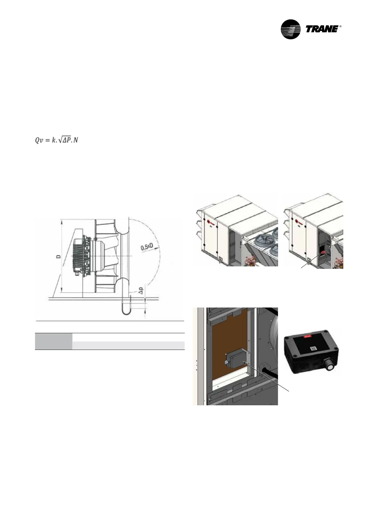
Supply fan Airow measurement option
The airow measurement option when selected is
associated with an air differential pressure sensor which
measures the pressure difference before the inlet nozzle
and inside the inlet nozzle.
Unit air ow can be calculated on the basis of the
differential pressure (difference in pressure of the static
pressures) in keeping with the following equation:
Qv in [m
3
/h] and ∆p in [Pa]
N - number of fans
k - takes into account the specic nozzle characteristics.
Connection on the unit side is acomplished via a pre-
mounted T tube connector. This tube connector is suited
for pneumatic hoses with an internal diameter of 4 mm.
k factors:
Fan diameter 400 450 500
k-factor 188 240 281
According to the option chosen, airow or fan RPM can
be read directly on the optional display or should be
determined by connecting a pressure drop meter to the
pre mounted T connector.
Setup is -20%/+30% variation versus factory setting
(190m
3
h-1/kW @ 250 Pa).
Refrigerant leak detector R454B
Refrigerant leak detector R454B is supplied and wired
in each unit selected with refrigerant R454B. Along
with this option, each unit selected with R454B is also
equipped by default by an airow rate sensor from
security point of view.
Refrigerant leak detector is installed between indoor coil
and indoor fans on the bottom, close to the door panel
which may have access to the indoor fans. See pictures
below.
The sensor is set to LFL (Lower Flammable Limit) about
0.5 % (500 ppm) at 23°C ambient temperature and RH
50%. Value of LFL is not adjustable
Installation
Refrigerant leak
detector R454B
Refrigerant leak
detector R454B
 Loading...
