24
CVHE-SVX02M-EN
Special Lift Requirements
NNOOTTIICCEE
OOiill LLoossss!!
FFaaiilluurree ttoo pprreevveenntt ooiill mmiiggrraattiioonn oouutt ooff tthhee ooiill ttaannkk
ccoouulldd rreessuulltt iinn eeqquuiippmmeenntt ffaaiilluurree oorr pprrooppeerrttyy--oonnllyy
ddaammaaggee..
TToo pprreevveenntt ooiill mmiiggrraattiioonn oouutt ooff tthhee ooiill ttaannkk dduurriinngg
lliiffttiinngg pprroocceedduurreess,, rreemmoovvee tthhee ooiill ffrroomm tthhee ooiill ttaannkk
iiff tthhee uunniitt wwiillll bbee lliifftteedd aatt aannyy aannggllee ggrreeaatteerr tthhaann
1155°° ffrroomm hhoorriizzoonnttaall eenndd--ttoo--eenndd.. IIff ooiill iiss aalllloowweedd ttoo
rruunn oouutt ooff tthhee ooiill ttaannkk iinnttoo ootthheerr aarreeaass ooff tthhee
cchhiilllleerr,, iitt wwiillll bbee eexxttrreemmeellyy ddiiffffiiccuulltt ttoo rreettuurrnn tthhee ooiill
ttoo tthhee ooiill ttaannkk eevveenn dduurriinngg ooppeerraattiioonn..
NNOOTTIICCEE
EEqquuiippmmeenntt DDaammaaggee!!
MMoovviinngg tthhee cchhiilllleerr uussiinngg aa ffoorrkk lliifftt ccoouulldd rreessuulltt iinn
eeqquuiippmmeenntt oorr pprrooppeerrttyy--oonnllyy ddaammaaggee..
DDoo nnoott uussee aa ffoorrkk lliifftt ttoo mmoovvee tthhee cchhiilllleerr!!
NNOOTTIICCEE
CCoommpprreessssoorr AAlliiggnnmmeenntt!!
FFaaiilluurree ttoo pprreesseerrvvee ccoommpprreessssoorr aalliiggnnmmeenntt ccoouulldd
rreessuulltt iinn eeqquuiippmmeenntt oorr pprrooppeerrttyy--oonnllyy ddaammaaggee..
LLiiffttiinngg tthhee ccoommpprreessssoorr//mmoottoorr aasssseemmbbllyy ffrroomm tthhee
sshheellllss wwiitthhoouutt ffaaccttoorryy--iinnssttaalllleedd ddoowweelliinngg iinn tthhee
ccoommpprreessssoorr ccaassttiinngg ffllaannggeess ccoouulldd rreessuulltt iinn
mmiissaalliiggnnmmeenntt ooff tthhee ccoommpprreessssoorr ccaassttiinnggss..
If the chiller cannot be moved using a standard chiller
lift, consider the following:
• When job site conditions require rigging of the
chiller at an angle greater than 45° from horizontal
(end-to-end), the unit may require removal of the
compressor. Contact Trane or an agent of Trane
specifically authorized to perform start-up and
warranty of Trane® products regarding the
disassembly and reassembly work. For more
information, refer to “Factory Warranty
Information,” p. 3.
NNoottee:: Disassembly and reassembly work includes
dowel-pinning the compressor and removing
it from the unit. Contact Trane or an agent of
Trane specifically authorized to perform start-
up and warranty of Trane
®
products for
specific rigging instructions. Do NOT attempt
to rotate the chiller onto its side.
• When lifting the chiller is either impractical or
undesirable, attach cables or chains to the jacking
slots shown in Figure 5, p. 23; then push or pull the
unit across a smooth surface. Should the chiller be
on a shipping skid, it is not necessary to remove the
skid from the chiller before moving it into place.
• If removal of the compressor or economizer
assembly is necessary to move the chiller to the
operating location, contact Trane. Also refer to
“Factory Warranty Information,” p. 3.
Unit Isolation
To minimize sound and vibration transmission through
the building structure and to ensure proper weight
distribution over the mounting surface, always install
isolation pads or spring isolators under the chiller feet.
NNoottee:: Isolation pads (refer to Figure 6, p. 24) are
provided with each chiller unless spring isolators
are specified on the sales order.
Specific isolator loading data is provided in the unit
submittal package. If necessary, contact your local
Trane sales office for further information.
IImmppoorrttaanntt:: When determining placement of isolation
pads or spring isolators, remember that the
control panel side of the unit is always
designated as the front side of the unit.
Isolation Pads
When the unit is ready for final placement, position
isolation pads (18-in. [457.2-mm] sides) end for end
under the full length of the chiller leg. The pads
measure 9 in. × 18 in. (228.6 mm x 457.2 mm) and on
some units there may be small gaps between pads.
Pads are provided to cover entire foot. Place pad flush
with the outside edge of the chiller foot and leave
excess material under the chiller.
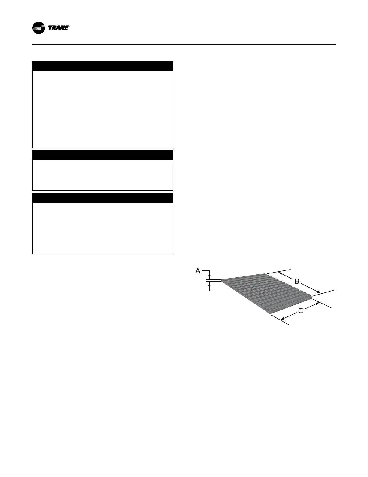
Figure 6. Isolation pad and dimensions
A = 3/8 in. (9.5 mm)
B = 18 in. (457.2 mm)
C = 9 in. (228.6 mm)
Remember that the chiller must be level within 1/16 in.
(1.6 mm) over its length and width after it is lowered
onto the isolation pads. In addition, all piping
connected to the chiller must be properly isolated and
supported so that it does not place any stress on the
unit.
Spring Isolators
Spring isolators should be considered whenever chiller
installation is planned for an upper story location. Base
isolator placement is shown in the following figure.
IInnssttaallllaattiioonn:: MMeecchhaanniiccaall
 Loading...


