68
CVHE-SVX02M-EN
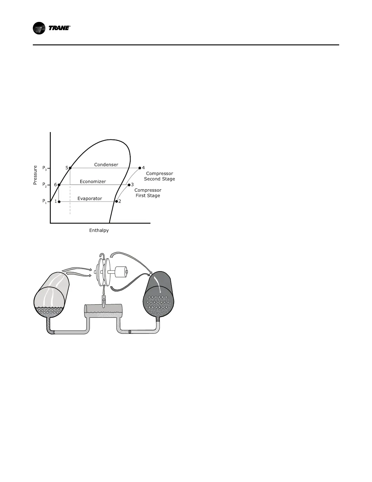
gaseous refrigerant through both stages of
compression (refer to Figure 47, p. 68). Notice that
some of the liquid refrigerant flashes to a gas because
of the pressure drop created by the orifice plate, thus
further cooling the liquid refrigerant. This flash gas is
then drawn directly from the economizer into the
second-stage impellers of the compressor. All
remaining liquid refrigerant flows out of the
economizer, passing through another orifice plate and
into the evaporator.
Figure 46. Pressure enthalpy curve
Figure 47. Refrigerant flow, 2-stage
Oil and Refrigerant Pump
Compressor Lubrication System
A schematic diagram of the compressor lubrication
system is illustrated in the following figure. Oil is
pumped from the oil tank (by a pump and motor
located within the tank) through an oil pressure
regulating valve designed to maintain a net oil
pressure of 18 to 22 psid (124.1 to 151.7 kPaD). It is then
filtered and sent to the oil cooler located in the
economizer and on to the compressor motor bearings.
From the bearings, the oil drains back to the manifold
and separator under the motor and then on to the oil
tank.
OOppeerraattiinngg PPrriinncciipplleess
 Loading...


