72
CVHE-SVX02M-EN
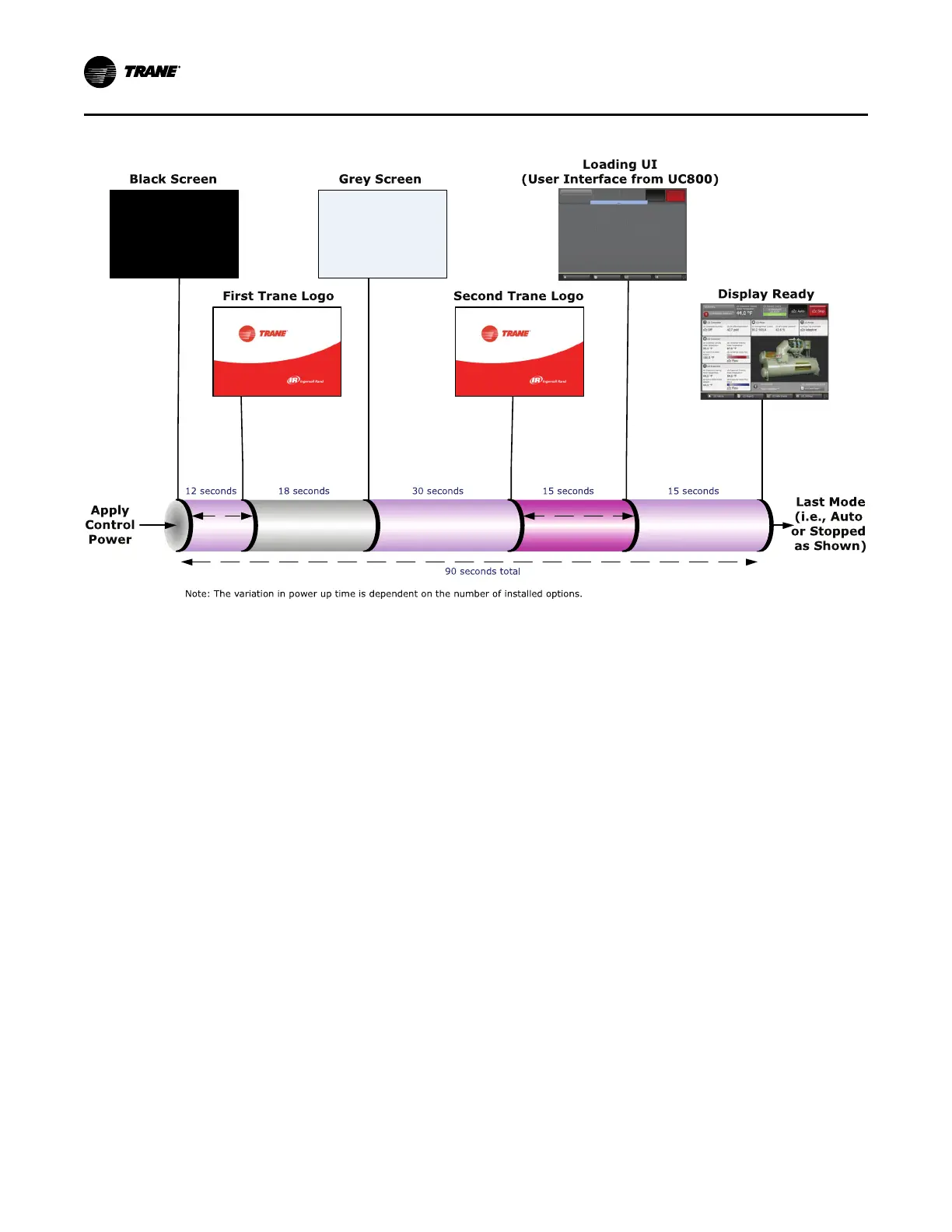
Figure 50. Sequence of operation: Tracer®® AdaptiView™™ power up
In the following diagrams:
• The time line indicates the upper level operating
mode, as it would be viewed in the Tracer®
AdaptiView™.
• The shading color of the cylinder indicates the
software state.
• Text in parentheses indicates sub-mode text as
viewed in the Tracer® AdaptiView™.
• Text above the time line cylinder is used to illustrate
inputs to the UC800. This may include user input to
the Tracer® AdaptiView™ touch screen, control
inputs from sensors, or control inputs from a
generic BAS.
• Boxes indicate control actions such as turning on
relays, or moving the inlet guide vanes.
• Smaller cylinders indicate diagnostic checks, text
indicates time-based functions, solid double arrows
indicate fixed timers, and dashed double arrows
indicate variable timers.
Start-up Sequence of Operation—Wye-
delta
Logic circuits within the various modules will
determine the starting, running, and stopping
operation of the chiller. When operation of the chiller is
required, the chiller mode is set at “Auto.” Using
customer-supplied power, the chilled water pump relay
is energized and chilled water flow must be verified
within 4 minutes and 15 seconds. The UC800 decides to
start the chiller based on the differential to start
setpoint. With the differential to start criteria met, the
UC800 then energizes condenser water pump relay
with customer-supplied power (refer to Figure 51, p.
73).
Based on the Restart Inhibit function and the
Differential to Start setpoint, the oil and refrigerant
pump is energized. The oil pressure must be at least
12 psid (82.7 kPaD) for 60 continuous seconds and
condenser water flow verified within 4 minutes and
15 seconds for the compressor start sequence to be
initiated.
The compressor motor starts in the “Wye”
configuration and then, after the compressor motor has
accelerated and the maximum phase current has
dropped below 85 percent of the chiller nameplate RLA
for 1.5 seconds, the starter transitions to the “Delta”
configuration.
SSttaarrtt--uupp aanndd SShhuutt--ddoowwnn
 Loading...


