30
CVHE-SVX02M-EN
(either flow or Delta-P) are required as shown on wiring
diagrams. These switches are used with control logic to
confirm flow prior to starting a unit and to stop a
running unit if flow is lost. For troubleshooting, a
viewable diagnostic is generated if a proof of flow
switch does not close when flow is required.
Evaporator and Condenser
Water Piping
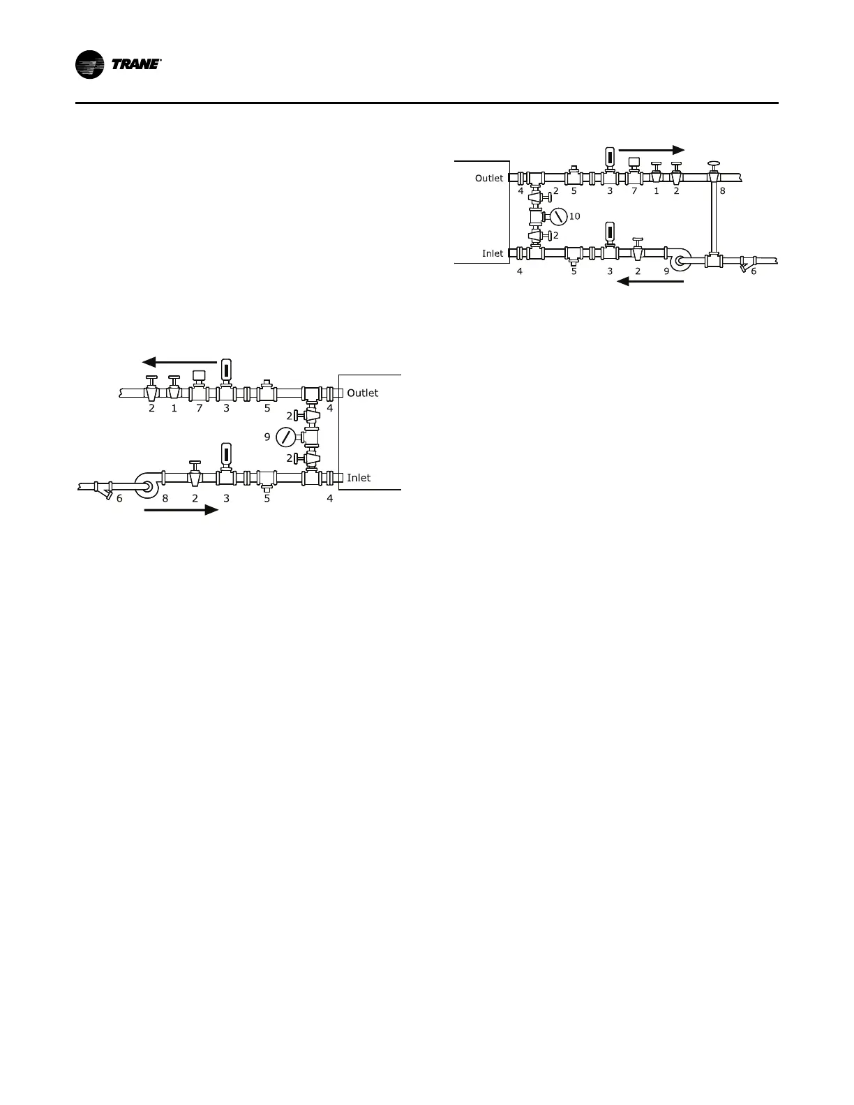
The following two figures illustrate the recommended
(typical) water piping arrangements for the evaporator
and condenser.
Figure 13. Typical evaporator water piping circuit
1. Balancing valve.
2. Gate (Isolation) valve or ball valve.
3. Thermometer (if field supplied).
4. Waterbox nozzle connection.
5. Drain, vent, and anode.
6. Strainer.
7. Chilled water flow switch (5S1). Flow switch 5S1
may be installed in either the entering or leaving leg
of the chilled water circuit.
8. Pump.
9. Pressure gauge. It is recommended to pipe the
gauge between entering and leaving pipes. A
shutoff valve on each side of the gauge allows the
operator to read either entering or leaving water
pressure.
Figure 14. Typical condenser water piping circuits
1. Balancing valve.
2. Gate (isolation) valve or ball valve.
3. Thermometer (if field supplied).
4. Waterbox nozzle connection.
5. Drain, vent, and anode.
6. Strainer.
7. Condenser water flow switch (5S2). Flow switch
5S2 may be installed in either the entering or
leaving leg of the chilled water circuit.
8. Three-way valve (optional).
9. Condenser water pump.
10. Pressure gauge. It is recommended to pipe a single
gauge between entering and leaving pipes.
NNootteess::
• Some type of field-supplied temperature
control device may be required to regulate
the temperature of the heat-recovery
condenser water circuit. For application
recommendations, refer to Heat Recovery
Seminar (Part 2): Systems/Equipment (AM-
FND-8).
• Install a bypass valve system to avoid
circulating water through the auxiliary shell
when the unit is shut down.
• On multiple-pass condensers, entering
condenser water must enter at the lowest
nozzle.
Piping must be arranged and supported to avoid stress
on the equipment. It is strongly recommended that the
piping contractor does not run pipe closer than 3 ft
(0.9 m) minimum to the equipment. This will allow for
proper fit upon arrival of the unit at the job site. Any
adjustment that is necessary can be made to the piping
at that time. Expenses that result from a failure to
follow this recommendation will NOT be paid by Trane.
Water piping connection sizes and components are
identified in Table 6, p. 31, Table 7, p. 31, and Table 8,
p. 32. Remember that with many waterboxes, the
entering and leaving evaporator water can be piped to
either waterbox connection when the tube bundles are
split vertically. However, large evaporator waterboxes
with entering and leaving connections not at the same
IInnssttaallllaattiioonn:: WWaatteerr PPiippiinngg
 Loading...


