34
CVHE-SVX02M-EN
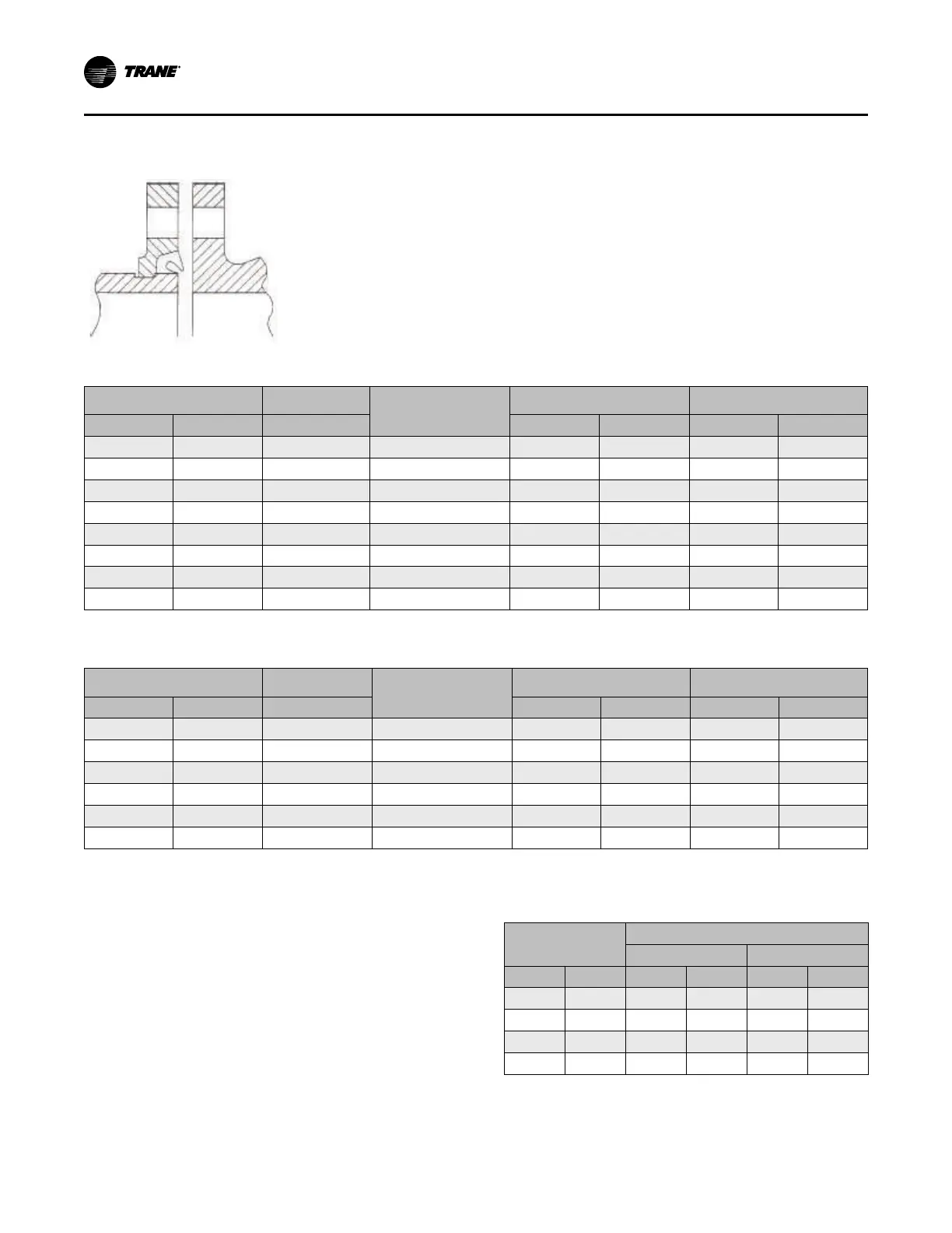
Figure 19. Typical Victaulic®® flange gasket
configuration
Table 9. Installation data for 150 psig (1034.2 kPaG) flange adapters (Style 741)
Nominal Pipe Size
Assembly Bolt
Size
(a)
Number of Assembly
Bolts Required
Bolt Pattern Diameter
Weight
in.
mm
in. in.
mm
lb
kg
4 114.3
5/8 x 3
8 7.5 191 7.7 3.5
5 141.3
3/4 x 3-1/2
8 8.5 216 9.3 4.2
6 168.3
3/4 x 3-1/2
8 9.5 241 10.3 4.7
8 219.1
3/4 x 3-1/2
8 11.75 298 16.6 7.5
10 273.0
7/8 x 1/4
12 14.25 362 24.2 11.0
12 323.9
7/8 x 1/4
12 17 432 46.8 21.2
14 355.6
1 x 4-1/2
12 18.75 476 75 34.0
16 406.4
1 x 4-1/2
16 21.25 540 90 40.8
(a)
Bolt size for conventional flange-to-flange connection. Longer bolts are required when flange washer must be used.
Table 10. Installation data for 300 psig (2068.4 kPaG) flange adapters (Style 743)
Nominal Pipe Size
Assembly Bolt
Size
(a)
Number of Assembly
Bolts Required
Bolt Pattern Diameter
Weight
in.
mm
in. in.
mm
lb
kg
4 114.3
3/4 x 3-3/4
8 7.88 200 15.3 6.9
5 141.3
3/4 x 4
8 9.25 235 17.7 8.0
6 168.3
3/4 x 4-1/2
12 10.63 270 23.4 10.6
8 219.1
3/4 x 4-3/4
12 13 330 34.3 15.6
10 273.0
1 x 5-1/4
16 15.25 387 48.3 21.9
12 323.9
1-1/8 x 5-3/4
16 17.75 451 70.5 32.0
(a)
Bolt size for conventional flange-to-flange connection. Longer bolts are required when flange washer must be used.
Bolt-Tightening Sequence for
Water Piping Connections
This section describes a bolt-tightening sequence for
flanges with flat gaskets or O-rings. Remember that
improperly tightened flanges may leak.
NNoottee:: Before tightening any of the bolts, align the
flanges. Flange bolt torque requirements are
provided in the following table.
Table 11. Flange bolt torque recommendations for O-
ring and flat-gasket piping connections
Bolt Size
Gasket Type
O-Ring
Flat
in.
mm
ft·lb N·m ft·lb N·m
3/8
9.5 25 34 12–18 16–24
1/2
13 70 95 33–50 45–68
5/8
16 150 203 70–90 95–122
3/4
19 250 339 105–155 142–210
NNoottee:: Bolt size is determined by the diameter of bolt shank.
IInnssttaallllaattiioonn:: WWaatteerr PPiippiinngg
 Loading...


