60
CVHE-SVX02M-EN
Terminal Clamps
NNOOTTIICCEE
UUssee CCooppppeerr CCoonndduuccttoorrss OOnnllyy!!
FFaaiilluurree ttoo uussee ccooppppeerr ccoonndduuccttoorrss ccoouulldd rreessuulltt iinn
eeqquuiippmmeenntt ddaammaaggee aass uunniitt tteerrmmiinnaallss aarree nnoott
ddeessiiggnneedd ttoo aacccceepptt ootthheerr ttyyppeess ooff ccoonndduuccttoorrss..
Terminal clamps are supplied with the motor terminals
to accommodate either bus bars or standard motor
terminal wire lugs. Terminal clamps provide additional
surface area to minimize the possibility of improper
electrical connections.
Wire Terminal Lugs
NNOOTTIICCEE
CCoommppoonneenntt DDaammaaggee!!
FFaaiilluurree ttoo eennssuurree tthhee ppoowweerr ssuuppppllyy wwiirriinngg aanndd
oouuttppuutt ttoo mmoottoorr wwiirriinngg aarree ccoonnnneecctteedd ttoo tthhee
pprrooppeerr tteerrmmiinnaallss ccoouulldd ccaauussee ccaattaassttrroopphhiicc ffaaiilluurree
ooff tthhee ssttaarrtteerr aanndd//oorr mmoottoorr..
Wire terminal lugs must be field supplied.
• Use field-provided, crimp-type wire terminal lugs
properly sized for the application.
NNoottee:: Wire size ranges for the starter line and load-
side lugs are listed on the starter submittal
drawings supplied by the starter
manufacturer or Trane. Carefully review the
submitted wire lug sizes for compatibility
with the conductor sizes specified by the
electrical engineer or contractor.
• On 4160V and below, a terminal clamp with a
3/8-in. (9.525-mm) bolt is provided on each motor
terminal stud; use the factory-supplied Belleville
washers on the wire lug connections. The following
figure illustrates the junction between a motor
terminal stud and terminal lug.
• Torque for this assembly is 24 ft·lb (32.5 N·m).
• Install but do NOT connect the power leads
between the starter and compressor motor. (These
connections will be completed under supervision of
a qualified Trane service engineer after the pre-start
inspection.)
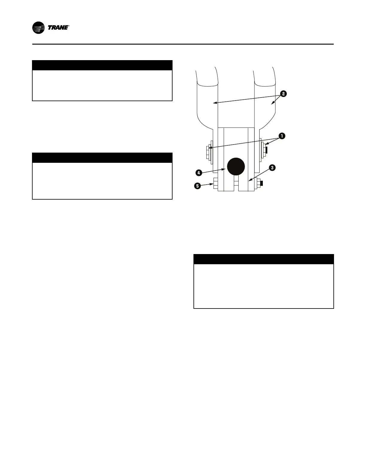
Figure 42. Terminal stud, clamp, and lug assembly
(4160V and below)
1. Belleville washer
2. Terminal lugs
3. Terminal clamp
4. Motor terminal stud
5. 3/8-in. bolt
Bus Bars
NNOOTTIICCEE
CCoommppoonneenntt DDaammaaggee!!
FFaaiilluurree ttoo ffoollllooww iinnssttrruuccttiioonnss bbeellooww ccoouulldd ccaauussee aann
eelleeccttrriiccaall sshhoorrtt wwhhiicchh ccoouulldd rreessuulltt iinn ccoommppoonneenntt
ddaammaaggee..
RReemmoovvee ddeebbrriiss ffrroomm iinnssiiddee tthhee CCPPTTRR ooppttiioonn
eenncclloossuurree ppaanneell bbeeffoorree ttuurrnniinngg tthhee ppoowweerr oonn..
Bus bars and extra nuts are available as a Trane option.
Install the bus bars between the motor terminals when
using a starter that is:
• A low-voltage Adaptive Frequency™ Drive (AFD)
• Across-the-line
• Primary reactor/resistor
• Autotransformer
• Customer-supplied
Connect T1 to T6, T2 to T4, and T3 to T5.
NNoottee:: Bus bars are not needed in medium-voltage or
high-voltage applications since only
three terminals are used in the motor and starter.
When attaching starter leads to 6.6 to 7kV motor
terminals, the 1/2-in.-13 brass jam nuts should be
tightened to a maximum torque of 18 to 22 ft·lb (24.4 to
29.8 N·m). Always use a second wrench to backup the
PPoowweerr SSuuppppllyy WWiirriinngg
 Loading...


