58
CVHE-SVX02M-EN
NNootteess::
• Verify PFCC voltage rating is greater than or
equal to the compressor voltage rating
stamped on the unit nameplate.
• Refer to the wiring diagrams that shipped
with the unit for specific PFCC wiring
information.
NNOOTTIICCEE
MMoottoorr DDaammaaggee!!
FFaaiilluurree ttoo wwiirree PPFFCCCCss iinnttoo tthhee ssttaarrtteerr ccoorrrreeccttllyy
ccoouulldd ccaauussee mmiissaapppplliiccaattiioonn ooff tthheessee ccaappaacciittoorrss
aanndd rreessuulltt iinn aa lloossss ooff mmoottoorr oovveerrllooaadd pprrootteeccttiioonn
aanndd ssuubbsseeqquueennttllyy ccaauussee mmoottoorr ddaammaaggee..
PPFFCCCCss mmuusstt bbee wwiirreedd oonnee ooff ttwwoo wwaayyss aass sshhoowwnn aass
eexxppllaaiinneedd iinn tthhee ffoolllloowwiinngg ffiigguurreess aanndd
aaccccoommppaannyyiinngg tteexxtt ((OOppttiioonn 11 aanndd OOppttiioonn 22))..
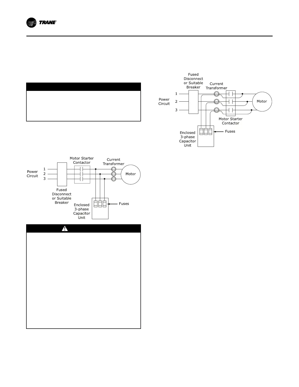
Figure 38. Option 1—PFCCs installed downstream of
starter contactor, upstream of current transformers
WWAARRNNIINNGG
HHaazzaarrddoouuss VVoollttaaggee ww//CCaappaacciittoorrss!!
FFaaiilluurree ttoo ddiissccoonnnneecctt ppoowweerr aanndd ddiisscchhaarrggee
ccaappaacciittoorrss bbeeffoorree sseerrvviicciinngg ccoouulldd rreessuulltt iinn ddeeaatthh oorr
sseerriioouuss iinnjjuurryy..
DDiissccoonnnneecctt aallll eelleeccttrriicc ppoowweerr,, iinncclluuddiinngg rreemmoottee
ddiissccoonnnneeccttss aanndd ddiisscchhaarrggee aallll mmoottoorr ssttaarrtt//rruunn
ccaappaacciittoorrss bbeeffoorree sseerrvviicciinngg.. FFoollllooww pprrooppeerr
lloocckkoouutt//ttaaggoouutt pprroocceedduurreess ttoo eennssuurree tthhee ppoowweerr
ccaannnnoott bbee iinnaaddvveerrtteennttllyy eenneerrggiizzeedd.. FFoorr vvaarriiaabbllee
ffrreeqquueennccyy ddrriivveess oorr ootthheerr eenneerrggyy ssttoorriinngg
ccoommppoonneennttss pprroovviiddeedd bbyy TTrraannee oorr ootthheerrss,, rreeffeerr ttoo
tthhee aapppprroopprriiaattee mmaannuuffaaccttuurreerr’’ss lliitteerraattuurree ffoorr
aalllloowwaabbllee wwaaiittiinngg ppeerriiooddss ffoorr ddiisscchhaarrggee ooff
ccaappaacciittoorrss.. VVeerriiffyy wwiitthh aann aapppprroopprriiaattee vvoollttmmeetteerr
tthhaatt aallll ccaappaacciittoorrss hhaavvee ddiisscchhaarrggeedd..
FFoorr aaddddiittiioonnaall iinnffoorrmmaattiioonn rreeggaarrddiinngg tthhee ssaaffee
ddiisscchhaarrggee ooff ccaappaacciittoorrss,, sseeee PPRROODD--SSVVBB0066**--EENN..
Simultaneously disconnect capacitors and load from
line power. If the capacitors are not switched offline
when the load is disconnected, they continue to add
capacitance to the electrical distribution system. A
leading power factor—too much capacitance—may
eventually develop. This overprotection causes poor
voltage regulation (i.e., voltage is high when the circuit
is unloaded, then drops as loads are added).
Figure 39. Option 2—PFCC wires routed through
current transformers
Size motor overload protection to account for
capacitor-supplied current. Overloads are typically set
to measure the total current drawn by the motor. When
PFCCs are used, they become the source of part of that
current. If the current they provide is not registered by
the overload protectors, potentially damaging
amperage can reach the motor. The simplest way to
ensure that the overloads detect all current supplied to
the motor is to position the PFCCs upstream of the
current transformers as shown in Figure 38, p. 58. If the
capacitor connection points are downstream of the
current transformers, route the PFCC leads through the
current transformers as shown in Figure 39, p. 58. This
ensures that the overloads register both line and
capacitor-supplied current.
Interconnecting Wiring
Typical equipment room conduit layouts with and
without unit-mounted starters are shown in the
following two figures.
IImmppoorrttaanntt:: The interconnecting wiring between the
starter panel, compressor, and control
panel is factory-installed with unit-mounted
starters. However, when a remote-mounted
starter is used, the interconnecting wiring
must be field-installed.
NNoottee:: Refer to starter submittal drawing for location of
incoming wiring to the starter.
PPoowweerr SSuuppppllyy WWiirriinngg
 Loading...


