Overview
7–2 iSTAR Ultra Installation and Configuration Guide
Overview
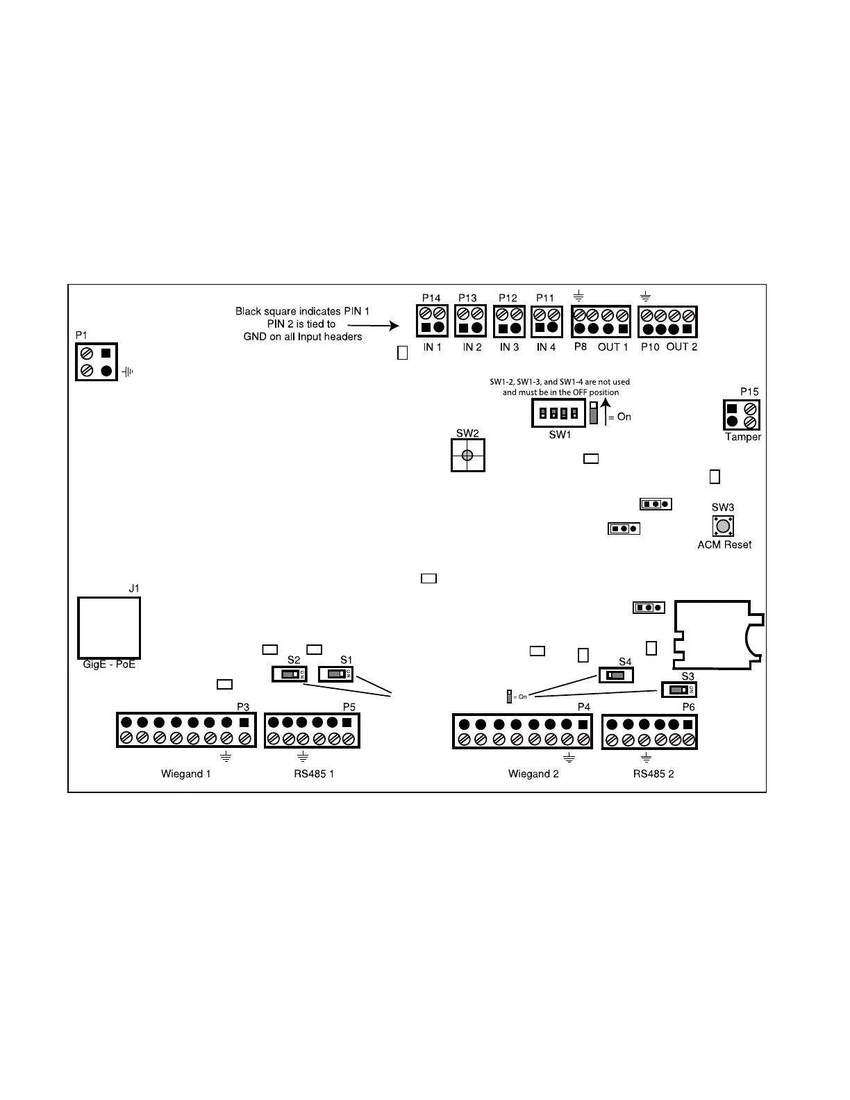
The IP-ACM module provides connection and management of the access control for two doors
through inputs, outputs, and reader interfaces. The IP-ACM can be powered by either 12V
supply or Power over Ethernet (PoE). It communicates to readers via wiegand interface or
RS485 interface, and it communicates to the GCM via TCP/IP over Ethernet. The IP-ACM
module also has AES256 network encryption from the unit to the GCM. The encryption
settings are determined by the GCM configuration. The maximum number of IP-ACM
modules supported per GCM is 32.
Figure 7-1: IP-ACM board
Switches and Jumpers
IP-ACM Reset - SW3
DIP Switch - SW1
SW1-2, SW1-3, and SW1-4 are not used and must be in the OFF position.
10
10
SW1-1 ON is Standalone Conguration
Position D of the rotary switch is factory reset.
All other positions are not used.
P9
P7
P2
J5
RS485 Termination Switches
DS3
DS4
DS9
DS7
DS8
DS5
DS12
DS1
DS11
DS2
24V Present
RS485_1 Rx
Communication LED
RS485_1 Tx
Reader_1 Power Enabled
RS485_2 Rx
Reader_2 Power Enabled
Relay_1 On
Relay_2 On
SD Connector
+12V
D+
+12V
+12V
+12V
D+
D-
D-
FD+
FD+
FD-
FD-
D0
D1
RED
YEL
GRN
BPR
D0
D1
RED
YEL
GRN
BPR
C
NC
NO
C
NC
NO
Local Power
RS485_2 Tx
PWR
For Output 1:
Pin 1 & 2 is dry select.
Pin 2 & 3 is wet select.
For Output 2:
Pin 1 & 2 is dry select.
Pin 2 & 3 is wet select.
Selects lock voltage:
Pin 1 & 2 for 12V.
Pin 2 & 3 for 24V.
7
8
9
A
B
C
D
E
F
0
1
2
3
4
5
6
1 2 3
1 2 3
1 2 3

 Loading...