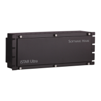
Overview
iSTAR Ultra Installation and Configuration Guide 7–3
SW1-1 is for standalone configuration. In normal operation mode, SW1-1 must be in the OFF
position. Refer to Initial Configuration for details.
RS - 485 Terminators
S1, S2, S3, S4
Rotary Switch - SW2
Position 0 is for normal operation. Position D of the rotary switch, SW2, is used for factory
reset. All other positions of the rotary switch are not used in this release.
GigE - PoE - J1
Ports and Connectors
Local Power - P1
Tamper - P15
Lock Voltage - P2
Select pin 1 and 2 for 12V power.
Select pin 2 and 3 for 24V power.
Output 1 - P7
Select pin 1 and 2 for dry select.
Select pin 2 and 3 for wet select.
Output 2 - P9
Select pin 1 and 2 for dry select.
Select pin 2 and 3 for wet select.
RS-485 Readers - P5, P6
Table 7-1: RS-485 Pin Signals
Pin Signal
1 +12V
2D+
3D-
4 GND

 Loading...