Overview
iSTAR Ultra Installation and Configuration Guide 7–5
For more information regarding other inputs available and details of configuration, refer to the
I/8 -CSI User Guide.
Power and Wiring
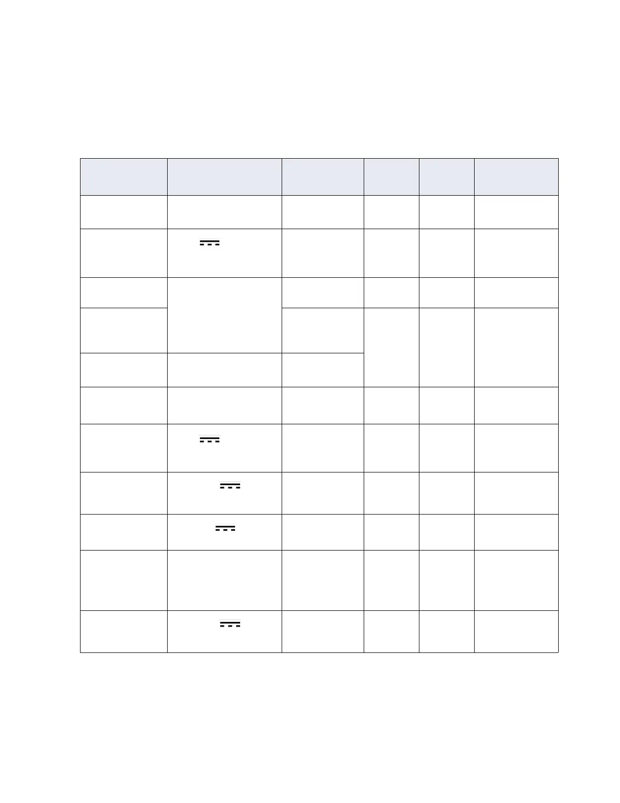
Table 7-2: Power and Wiring Requirements for the IP-ACM
Signal Power Requirements To AWG Shield
Maximum
Length
RS-485 Comm, Data
Full duplex 4 wire
RM & I/O modules 22 Yes 4000ft (1212m)
RS-485 Power
12Vdc
1
RM & I/O modules 22/18 Yes Range of 600ft to
1500ft depends on
AWG
2
RJ45-Ethernet Level 3 Switch,
Hub, or Host
CAT-5E or
better
No 328ft (100m)
Request to Exit
(REX
or RTE)
Switch Contact 22/18 No 2000ft (606m)
Door State Monitor
(DSM)
Switch Contact
Supervised Input
(UL)
3
Input 22 Yes 2000ft (606m)
Reader Data (Direct
Wiegand Connec-
tion)
12Vdc
4
Proximity/Wiegand
signaling read
head
22
20
18
Yes 200ft (60.96m)
300ft (91.4m)
500ft (152.4m)
Wet Relay Contacts
12 or 24Vdc
(jumper
selectable), 0.5A (per lock)
5
Dry Relay Contacts
0 to 30Vdc , 5A max.
NO, 3A max. NC
Power over Ethernet
(PoE)
IEEE 802.3af (PoE) and
802at (PoE Plus), 25.5W
max. LLDP supported for
PoE Plus
6
Switch Contact 24 Yes 328ft (100m)
Local Power
12 or 24Vdc , 32W
max.
7
P1 18 No Dependent on con-
figuration
1.It is important to note that the aggregate load of each pair of RS-485 and Wiegand connections together must not exceed
750mA. Each set of RS-485 and Wiegand can support 750mA.
2.Check wire lengths to verify that voltage drops are acceptable. Calculations are based on a single RM-4 reader with key-
pad and LCD (250mA). Using 22AWG, distance = 600ft. (.0165 ohms/ft.). Using 18AWG, distance = 1500ft. (.0065 ohms/
ft.).

 Loading...