Front Matter Sageon Micro Power Module Manual
PM990-4207-00, Rev 6
i
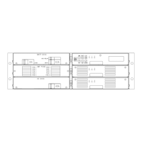
Rack Mounted Sageon Micro Power Shelf Module
Transporting and Seismic Statement
1.0 Transporting the Rack Mounted Sageon Micro Power Module Shelf.
1.1 The Power shelf is initially installed into a standard 19” rack (23” rack with extension plates)
without either the Controller or the Micro Sageon Rectifiers in place.
1.2 The Controller and Rectifiers must be packaged separately (not installed in the rack) when the
rack is being transported via ground or air. The system is not designed for the Controller or
Rectifiers to be transported while mounted to the Power shelf.
1.3 The Controller and Rectifiers must not be installed in the rack while the rack is being handled and
positioned into its designated “on-site” final location.
1.4 It is standard procedure for the rack, with Power shelf assembled (without either Controller or
Rectifiers installed), to be transported in a vertical position.
1.5 Transporting a crated rack system in a horizontal position is acceptable when the rack height
exceeds the standard trailer height. The Controller and Rectifiers must be packaged separately (not
installed in the rack) when the rack is being transported via ground or air.
2.0 Mounting the Power Shelf to a Rack On-Site.
2.1 The Power shelf mounts into a standard 19” rack using 12-24 screws. A minimum of four screws
are required to secure the Power shelf into the rack. It is recommended to initially install the
Power shelf into the rack without either the Controller or the Micro Sageon rectifiers in place.
3.0 Seismic Statement.
3.1 The Sageon Micro Power Module and/or the Rack Mounted Shelf design does not include, either
in the construction or in the assembly, the ability to withstand the lateral seismic forces or seismic
loading induced by earthquakes.
 Loading...