More information
‣
Installation accessories (optional) (page 14)
3.3 Wiring
Before you connect an HMP60 or HMP110 series probe to a device, it is
recommended to power o the device.
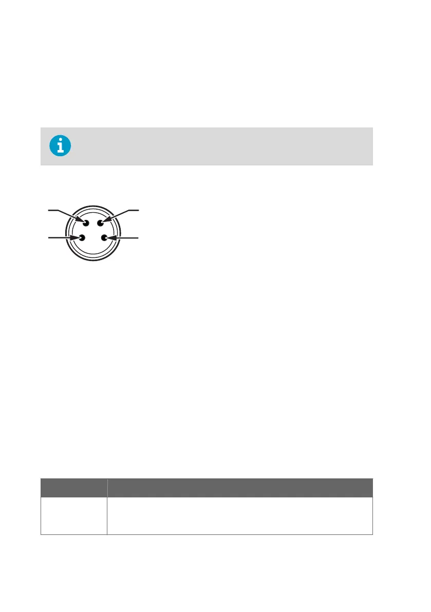
For a secure connection to the probe, connect to the 4-pin M8 connector using a threaded
connector.
Figure 13 M8 4-pin male connector
Pin-out of HMP60 / HMP63 / HMP110 analog / HMP113 / HMP110T
1 5 ... 28 VDC (V
out
0 ... 1 / 0 ... 2.5 V)
8 ... 28 VDC (V
out
0 ... 5 / 1 ... 5 V)
2 Channel 1: RH / Td / T
0 ... 1 / 2.5 / 5 V, 1 ... 5 V
3 GND / AGND
4 Channel 2: RH / Td / T
0 ... 1 / 2.5 / 5 V, 1 ... 5 V
(HMP110T has no output on channel 2)
Pin-out of HMP110REF / HMP110 digital
1
5 ... 28 VDC
2 RS-485: - / B
3 GND
4 RS-485: + / A
The grounding method depends on the probe and the installation type.
Table 5 Grounding methods
Probe Grounding method
HMP63
HMP113
Vaisala recommends to use a shielded cable and connect the shield to ground.
In the shielded cables supplied by Vaisala, the threaded connector connects
the shield to the probe housing.
HMP60 and HMP110 Series User Guide M211060EN-J
24

 Loading...