Vertiv | NetSure 7100 Series Quick Start Guide (QS582127000) | Rev. T
Make External Alarm, Reference, Monitoring, and Control Connections
Refer to External Alarm, Reference, Monitoring, and Control Connections in the MAKING ELECTRICAL
CONNECTIONS section of the Installation Instructions (IM582127000) for complete procedures.
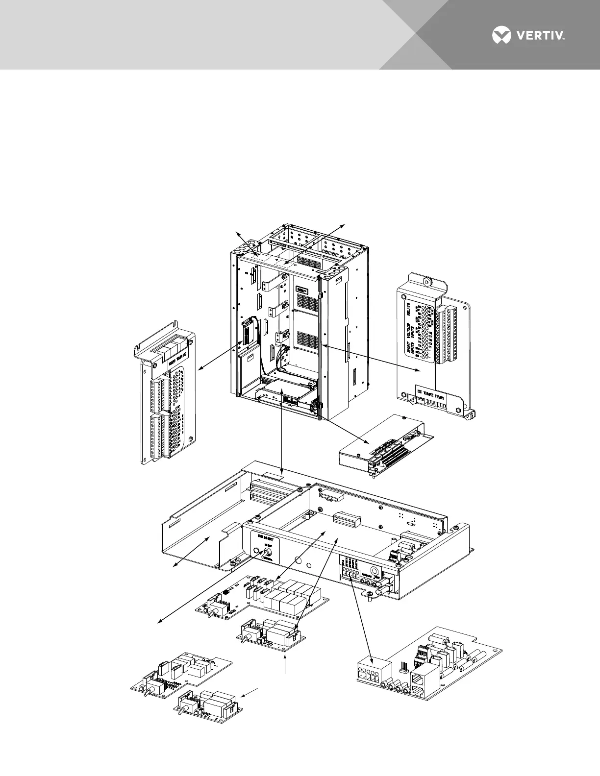
Circuit Card Locations
Refer to Figure 30.
Figure 30:
Circuit Card Locations
Opt
iona
l S
M-D
U+ a
nd
Shunt Interface Board
4-
R
ow
C
a
bi
n
et
Sh
o
w
n
,
O
t
h
e
r
s
S
i
m
i
l
a
r
(
F
r
o
n
t
D
o
o
r
R
e
m
o
v
e
d
i
n
Ill
ust
rati
on
f
or
Cl
a
ri
ty
)
Co
ntr
oll
er
(Main Ba
y)
S
M-D
U
(S
up
pl
em
en
ta
l Ba
ys
)
M
ounti
ng Posit
ion
Syste
m Interfac
e
Circuit Ca
rd
OR
Optiona
l LVD
Driv
er Circu
it Car
d
Op
tiona
l LVD
I
nhi
bit S
witch
(f
actory
installed
if option s
pecifie
d)
Optional LVD Dri
ver
Lite
Circuit Card
O
ptional Ma
nual Bat
tery
Disc
onnect Circui
t Card
(Main Bay Only)
IB2 (
Mai
n Ba
y O
nl
y)
(Int
erf
ace
Boar
d)
(located on inside side panel)
O
p
ti
on
a
l E
IB
(
Ma
in
B
ay
On
l
y)
(Extended Interface Board)
(
lo
ca
t
ed
o
n i
ns
i
de
si
d
e p
an
e
l)
Optional IB4 (Main Bay Only)
(S
e
co
nd
E
th
er
n
et
P
or
t B
o
ar
d)
Optiona
l Second IB2 or EIB (Main Bay Only)
(underside of cover)

 Loading...


