Vertiv | NetSure 7100 Series Quick Start Guide (QS582127000) | Rev. T
Table 5:
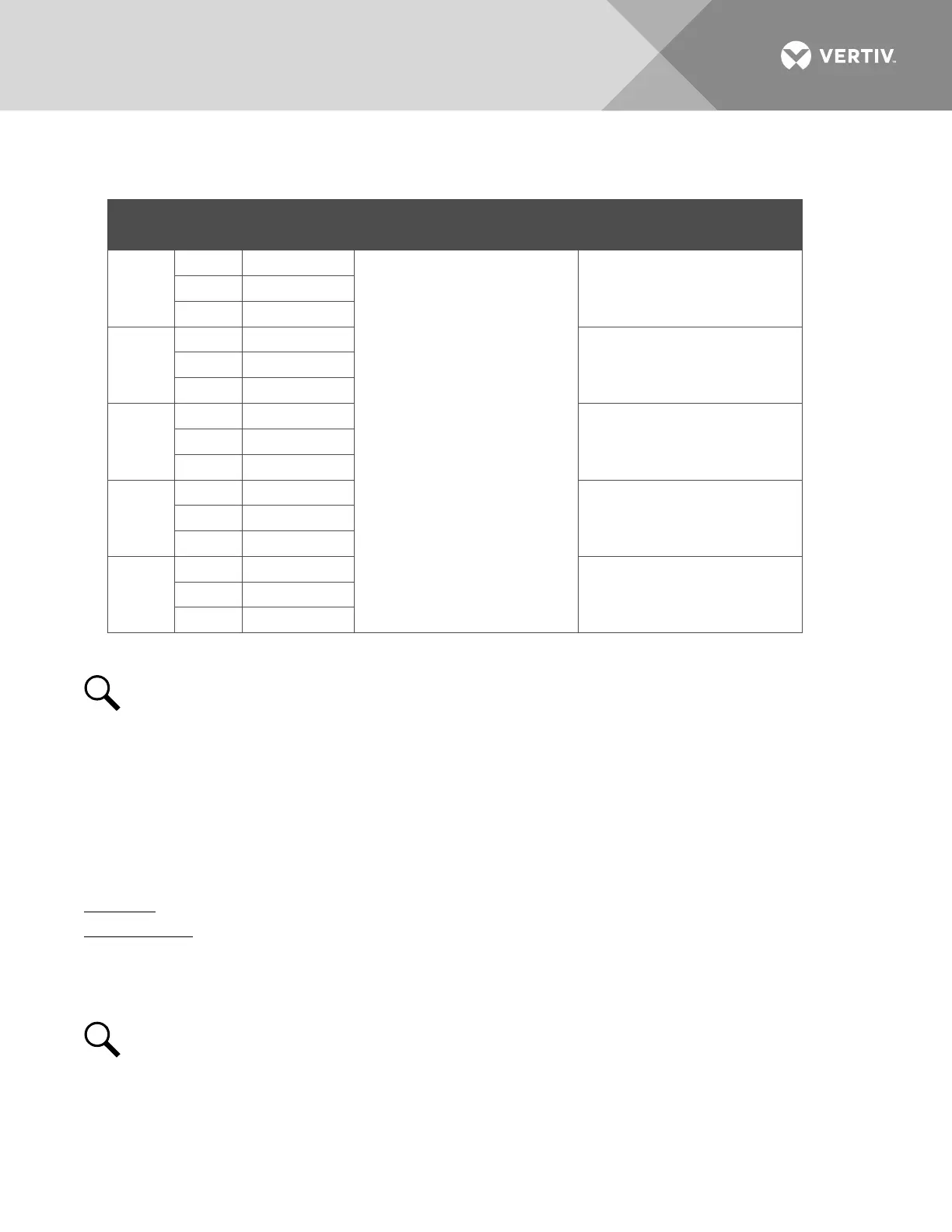
Programmable Relay Outputs – EIB
Programmable
Relay Output
Alarms Assigned to this
Relay (Default)
Alarms Assigned to this
Relay (Custom)
9
NO J8-5
The relays may be
preprogrammed for specific
functions. Refer to the
configuration drawing (C-
drawing) supplied with your
system for your system’s
specific configuration.
COM J8-3
NC J8-1
10
NO J8-6
COM J8-4
NC J8-2
11
NO J9-5
COM J9-3
NC J9-1
12
NO J9-6
COM J9-4
NC J9-2
13
NO J7-6
COM J7-4
NC J7-2
NOTE!
The relays energize during an alarm condition, closing the contacts between the C and NO
terminals, and opening the contacts between the C and NC terminals.
Refer to the configuration drawing (C-drawing) supplied with your system for your system’s specific
relay labeling.
Optional SM-DU+ and Shunt Interface Board
The optional SM-DU+ and Shunt Interface Board provides connections for up to twenty-five (25) shunt inputs.
Inputs are factory connected to any distribution positions/devices containing shunts. Refer to Figure 35.
Procedure
Current Inputs: Connect up to twenty-five (25) shunt inputs to the Shunt Interface Board. Observe proper
polarity. Note that some inputs may be factory connected, depending on distribution devices installed. Refer to
the ACU+ Instructions (UM1M820BNA or UM1M820DNA400) or NCU Instructions (UM1M830BNA) for
programming information for the unused inputs.
NOTE!
The shunt needs to be installed in the hot (-48V) bus. Connect the plus side of the shunt to the
positive shunt input on the SM-DU+. Connect the negative side of the shunt to the negative shunt input
on the SM-DU+.

 Loading...


