ENGLISH - 3
2. Installation of the BUS system
• For the connections, use a VIMAR 01840 insulated twisted
pair (2 x 0.5 mm
2
, rated voltage 300/500 V); The twisted
pair distributes the power (29 V d.c.) as well as the device
control and logic signals.
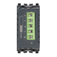
• The devices can be connected in any order, observing the
polarities marked on the terminals.
• At all points on the bus, the voltage should never drop
below 20 V. In particular, check the points furthest from
the power supply, and the most heavily loaded sections
of cable.
• The total current draw of the various devices should not
exceed the rated current of the power supply.
Warning! The current draw of a device tends to increase
when the supply voltage drops (for the current draw of
each device, refer to the corresponding “Technical charac-
teristics”).
• The bus system can be powered by 1 or 2 power sup-
plies, each with its choke (diagram on pg. 4).
• Maximum length of bus cable with 1 power supply:
250m.
• Maximum length of bus cable with 2 power supplies:
500 m. For an optimal load distribution, connect the two
power supplies at opposite ends of the bus.
• In the case of “star” bus topology, avoid creating exces-
sively long “rays” with few devices on them; it is recom-
mended to not exceed a length of 50 m if there is no more
than one device on the cable section, or 100 m if there
are no more than 5 devices on each cable section.
Ideally, the devices should be evenly distributed between
each of the star-connected cable sections.
 Loading...