Software Installation and Connections 11
© 2015 Vision Engraving Systems
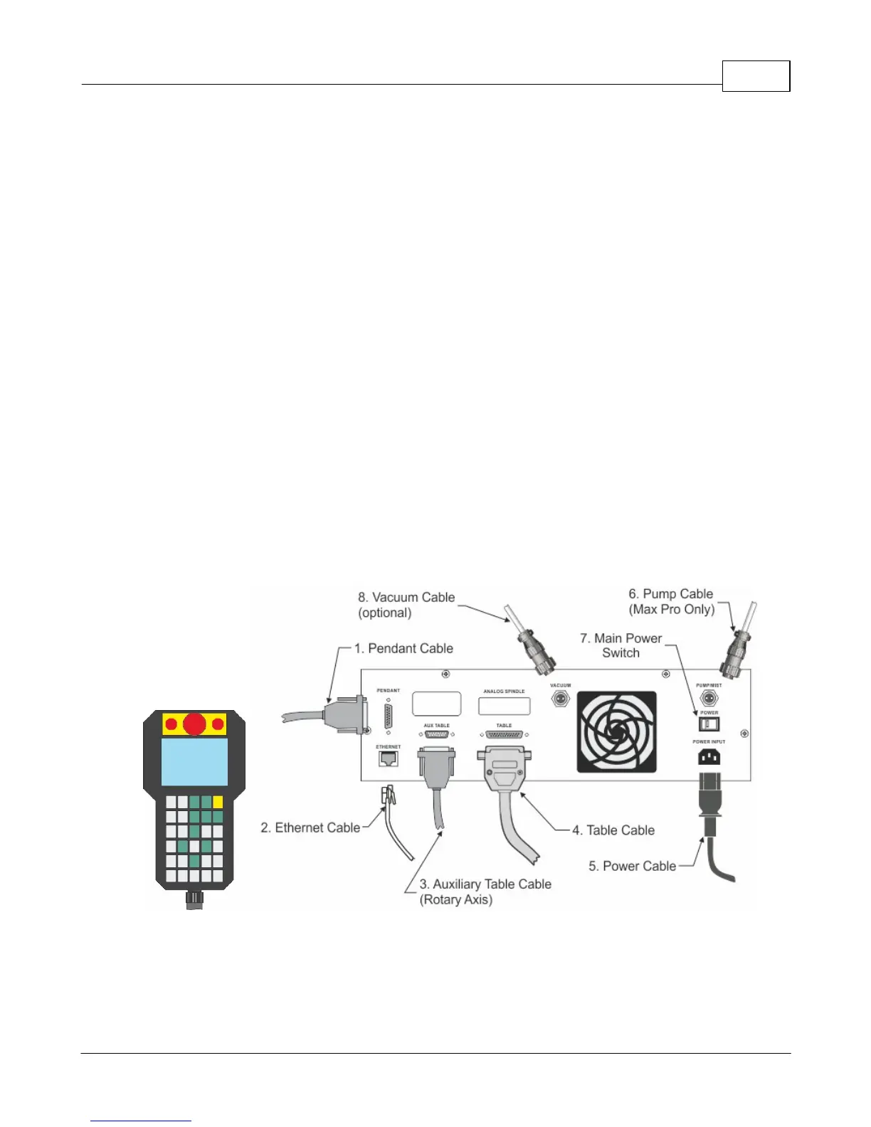
2.2 Max Pro Connections
The Vision Max Pro machine has an integrated controller inside the base of the machine. The machine
need to have the following cables connected to the controller.
1. The engraver's Pendant is connected to the Pendant cable port.
2. The Ethernet Cable from your computer, hub or network is connected to the Ethernet port.
3. The Auxiliary Table Cable is connected to the Aux Table port and powers the machine's rotary axis.
4. The Table Cable connects from 25 pin connector on the engraver to the Table port.
5. The Power Cable connects a 110 - 220 VAC electrical source to the controller and powers the
controller, table and spindle.
6. The Pump Cable (Max Pro only) connects to the Pump/Mist port and powers the machine's water
pump for glass engraving.
7. Main Power switch (for reference only)
8. If you machine was equipped with the optional Vacuum Chip Removal System, the Vacuum Cable
from the vacuum pump will connect to the Vacuum port.
Series 4 Pendant and Integrated Controller Connections
 Loading...