Manual Manual 37223E 37223E easYgen-3000 easYgen-3000 Series Series (Package (Package P1) P1) - - Genset Genset ControlControl
Page Page 14/67 14/67 © © WoodwardWoodward
Clamp Fastener InstallationClamp Fastener Installation
For installation into a For installation into a door panel with the fastening clamps, proceed as follodoor panel with the fastening clamps, proceed as follows:ws:
1.1.
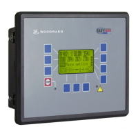
Panel cutoutPanel cutout
Cut out the panel according to Cut out the panel according to the dimensions inthe dimensions inTable 4-1.Table 4-1.
Note:
Note:
Don't drill the holes if Don't drill the holes if you want to use the clamp fasteners. If the holes areyou want to use the clamp fasteners. If the holes are
drilled into the pdrilled into the panel, the clamp fasteners cannot be used anymore!anel, the clamp fasteners cannot be used anymore!
cut-out
cut-out
186,0186,0
138,0138,0
R3,5R3,5
Rmax:Rmax:
2.2.
Remove terminalsRemove terminals
Loosen the wire connection terminal screws on the back of the unit andLoosen the wire connection terminal screws on the back of the unit and
remove the wire connection terminal strip if required.remove the wire connection terminal strip if required.
3.3.
Insert screws in clampsInsert screws in clamps
Insert the four clamping screws into the clamp inserts from Insert the four clamping screws into the clamp inserts from the shown sidethe shown side
(opposite of the nut insert) (opposite of the nut insert) until they are almost flush. Do not completelyuntil they are almost flush. Do not completely
insert the screws into the clamp inserts.insert the screws into the clamp inserts.
4.4.
Insert unit into cutoutInsert unit into cutout
Insert the unit into the panel cutout. Verify that the unit fits correctly inInsert the unit into the panel cutout. Verify that the unit fits correctly in
the cutout. If the panel cutout the cutout. If the panel cutout is not big enough, enlarge it accordis not big enough, enlarge it accordingly.ingly.
5.5.
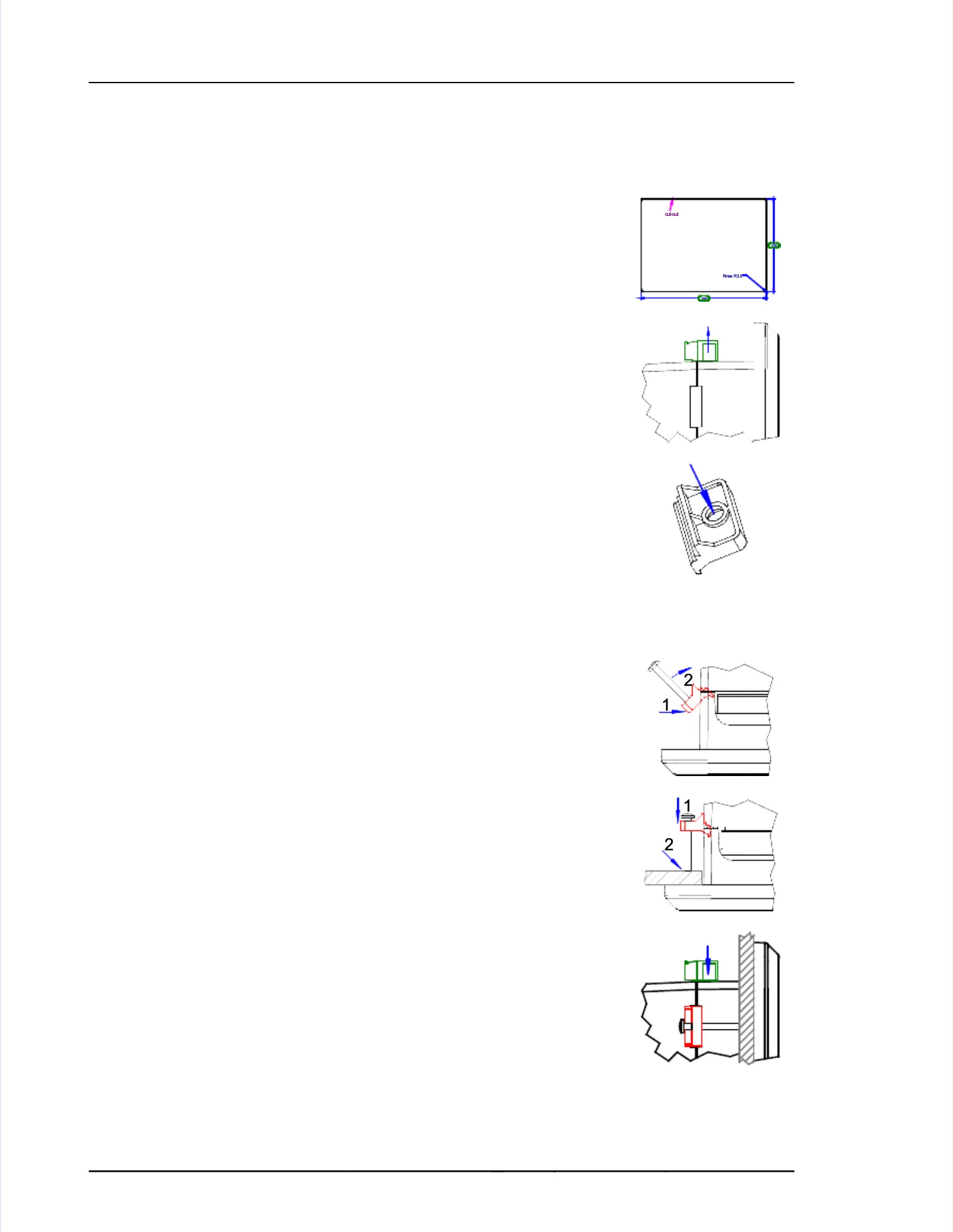
Attach clamp insertsAttach clamp inserts
Re-install the clamp inserts by tilting the insert to a 45° angle. (1) InsertRe-install the clamp inserts by tilting the insert to a 45° angle. (1) Insert
the nose of the insert into the nose of the insert into the slot on the side of the slot on the side of the housing. (2) Raise thethe housing. (2) Raise the
clamp insert so that it is parallel to the control panel.clamp insert so that it is parallel to the control panel.
11
22
6.6.
Tighten clamping screwsTighten clamping screws
Tighten the clamping screws (1) until the control Tighten the clamping screws (1) until the control unit is secured to theunit is secured to the
control panel (2). control panel (2). Over tightening of these screws may result in the clampOver tightening of these screws may result in the clamp
inserts or the housing breaking. Do not exceed tinserts or the housing breaking. Do not exceed the recommended tighten-he recommended tighten-
ing torque of 0.1 Nm.ing torque of 0.1 Nm.
11
22
7.7.
Reattach terminalsReattach terminals
Reattach the wire connection terminal strip (1) Reattach the wire connection terminal strip (1) and secure them with theand secure them with the
side screws.side screws.
 Loading...